Chapter 2 Switch Installation
Mounting the Switch
1
2
3 Desk or shelf |
Mounting tray
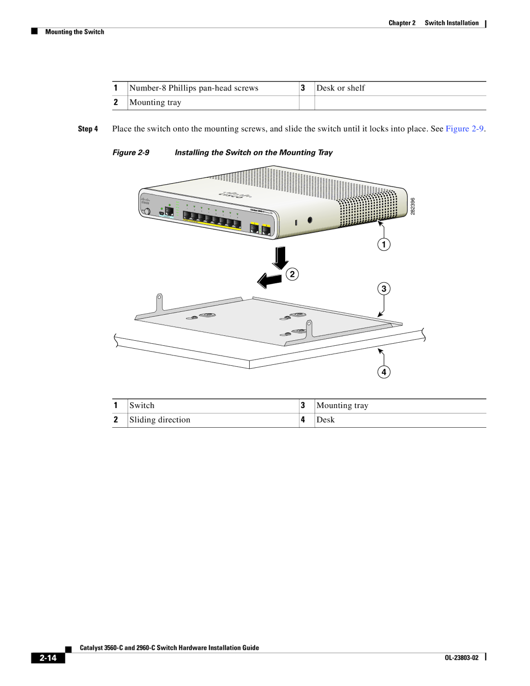
Step 4 Place the switch onto the mounting screws, and slide the switch until it locks into place. See Figure
Figure 2-9 Installing the Switch on the Mounting Tray
|
|
|
| SYST |
|
|
|
|
|
|
|
|
|
|
|
|
|
|
|
| STAT |
|
|
|
|
|
|
|
|
|
|
|
|
|
|
|
| DPLX | 1 |
|
|
|
|
|
|
|
|
|
|
|
MODE |
|
|
| SPD |
| 2 | 3 |
|
|
|
|
|
|
|
| |
|
|
|
| PoE |
|
|
|
| 4 | 5 | 6 |
|
|
| Series | PD |
|
| C | ONSOLE | PD |
|
|
|
|
|
| 7 |
|
|
|
| |
|
|
|
|
|
|
|
|
|
|
|
| 8 |
|
|
| |
|
|
|
|
| POWER |
|
|
|
|
|
|
|
|
|
|
|
|
|
|
|
| OVER | ET |
|
|
|
|
|
|
|
|
| |
|
|
|
|
|
|
|
|
|
|
|
|
|
|
| ||
|
|
|
|
|
|
| HERNET |
|
|
|
|
| 1 |
|
| |
|
|
|
|
|
|
|
|
|
|
|
|
|
|
| ||
|
|
|
|
|
|
|
|
|
|
|
|
| 2 |
| ||
1
2
3
4
1 | Switch | 3 | Mounting tray |
2 | Sliding direction | 4 | Desk |
|
|
|
|
282396
| Catalyst |