Chapter 2 Switch Installation
Mounting the Switch
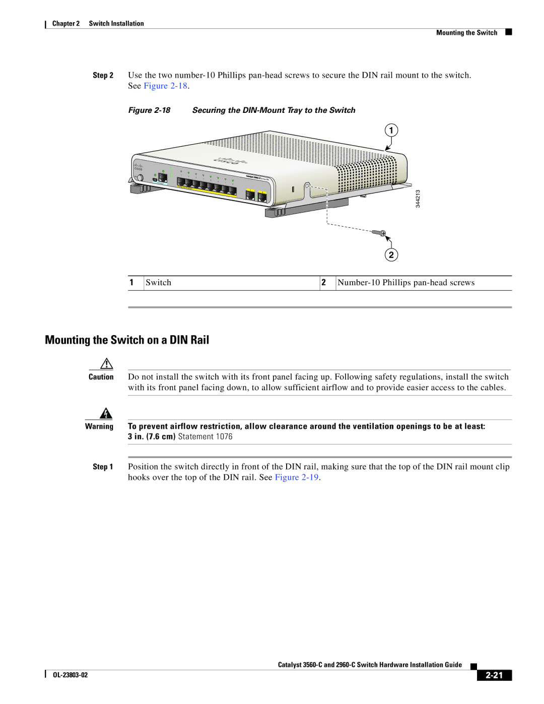
Step 2 Use the two
Figure 2-18 Securing the DIN-Mount Tray to the Switch
1
|
|
| SYST |
|
|
|
|
|
|
|
|
|
|
|
|
|
|
|
| STAT |
|
|
|
|
|
|
|
|
|
|
|
|
|
|
|
| DPLX | 1 |
|
|
|
|
|
|
|
|
|
|
|
|
MODE |
|
| SPD |
| 2 | 3 |
|
|
|
|
|
|
|
|
| |
|
|
| PoE |
|
|
|
| 4 | 5 | 6 |
|
|
| Series | PD |
|
|
| CONSOLE | PD |
|
|
|
|
|
| 7 | 8 |
|
|
|
| |
|
|
|
|
|
|
|
|
|
|
|
|
|
|
|
| |
|
|
|
|
|
|
|
|
|
|
|
|
|
|
|
|
|
|
|
|
| POWER |
|
|
|
|
|
|
|
|
|
|
|
|
|
|
|
|
| OVER | ETHERNET |
|
|
|
|
| 1 |
|
| 3 | |
|
|
|
|
|
|
|
|
|
|
|
|
| ||||
|
|
|
|
|
|
|
|
|
|
|
|
|
| |||
|
|
|
|
|
|
|
|
|
|
|
| 2 |
| |||
|
|
|
|
|
|
|
|
|
|
|
|
|
|
|
| 34421 |
2
1
Switch
2
Mounting the Switch on a DIN Rail
Caution Do not install the switch with its front panel facing up. Following safety regulations, install the switch with its front panel facing down, to allow sufficient airflow and to provide easier access to the cables.
Warning To prevent airflow restriction, allow clearance around the ventilation openings to be at least: 3 in. (7.6 cm) Statement 1076
Step 1 Position the switch directly in front of the DIN rail, making sure that the top of the DIN rail mount clip hooks over the top of the DIN rail. See Figure
|
| Catalyst |
|
| |
|
|
| |||
|
|
|
| ||
|
|
|
| ||