Chapter 2 Switch Installation
Mounting the Switch
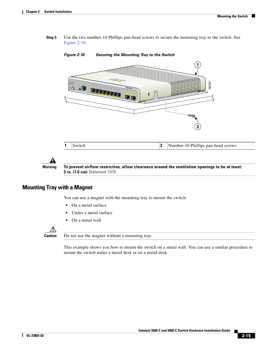
Step 5 Use the two
Figure 2-10 Securing the Mounting Tray to the Switch
1
MODE
CONSOLE
SYST STAT DPLX SPD PoE PD
1 | 2 | 3 |
|
|
|
|
|
|
| |
|
|
| 4 | 5 | 6 |
|
|
| Series | |
|
|
|
|
|
| 7 |
|
|
| |
|
|
|
|
|
|
| 8 |
|
| |
POWER | OVER | ETHERNET |
|
|
|
|
| 1 |
| |
|
|
|
|
|
|
| ||||
|
|
|
|
|
|
|
| |||
|
|
|
|
|
|
|
|
| ||
|
|
|
|
|
|
|
| 2 | ||
PD
282397
2
1
Switch
2
Warning To prevent airflow restriction, allow clearance around the ventilation openings to be at least: 3 in. (7.6 cm) Statement 1076
Mounting Tray with a Magnet
You can use a magnet with the mounting tray to mount the switch:
•On a metal surface
•Under a metal surface
•On a metal wall
Caution Do not use the magnet without a mounting tray.
This example shows you how to mount the switch on a metal wall. You can use a similar procedure to mount the switch under a metal desk or on a metal desk.
|
| Catalyst |
|
| |
|
|
| |||
|
|
|
| ||
|
|
|
| ||