Chapter 2 Switch Installation
Mounting the Switch
Step 1 Locate the screw template. The template is used to align the mounting screw holes.
Note Figure
Step 2 Position the screw template so that the two
For the best support of the switch and cables, make sure that you attach the switch securely to a wall stud or to a firmly attached plywood mounting backboard.
Step 3 Peel the adhesive strip off the bottom of the screw template.
Step 4 Attach the screw template to the wall.
Step 5 Use a
Step 6 Insert three screws in the slots on the screw template, and tighten until they touch the top of the screw template.
Step 7 Remove the screw template from the wall.
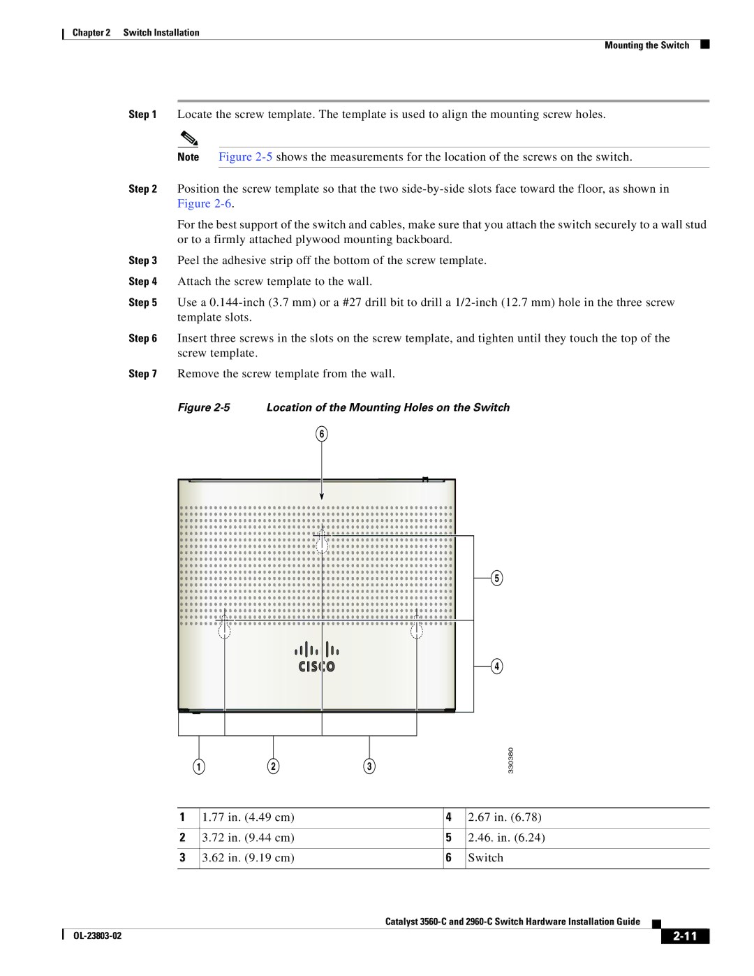
Figure 2-5 Location of the Mounting Holes on the Switch
6
5
4
1 | 2 | 3 |
330380
| 1 | 1.77 in. (4.49 cm) |
| 4 | 2.67 in. (6.78) | ||||
|
|
|
|
|
| ||||
2 | 3.72 in. (9.44 cm) |
| 5 | 2.46. in. (6.24) | |||||
|
|
|
|
|
| ||||
3 | 3.62 in. (9.19 cm) |
| 6 | Switch | |||||
|
|
|
|
|
|
|
|
| |
|
|
|
| Catalyst |
|
| |||
|
|
|
|
| |||||
|
|
|
|
|
|
|
|
|
|
|
|
|
|
|
|
| |||
|
|
|
|
|
|
| |||