What about connecting application nodes?
Remaining switch ports can be used to connect application nodes and their remote management controllers into the Cassatt Active Response environment. In general, distribute the connections evenly between the switches and the application nodes (both the application node NICs and their associated remote management controller NICs) For more information, see the Info Central site for detailed information on setting
up application nodes.
Racking and cabling guidelines
To cable your control nodes to the network switches according to Figure 1, follow these steps. Remember that this sample configuration uses four network switches, so use these instructions as a guideline for your own configuration.
1.Rack all switches and control node hardware according to the vendor’s documentation and/or the site policy. For lack of any other policy, rack the heaviest of the following pieces of equipment on the bottom:
•Cisco switches
•Power distribution units (PDUs)
•Control nodes
•Application nodes
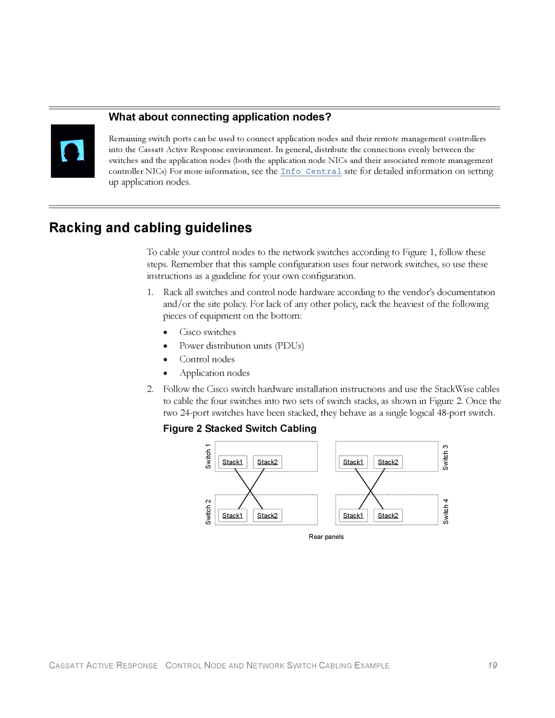
2.Follow the Cisco switch hardware installation instructions and use the StackWise cables to cable the four switches into two sets of switch stacks, as shown in Figure 2. Once the two
Figure 2 Stacked Switch Cabling
Switch 2 Switch 1
Stack1 ![]()
![]() Stack2
Stack2
Stack1 ![]()
![]() Stack2
Stack2
Stack1 ![]()
![]() Stack2
Stack2
Stack1 ![]()
![]() Stack2
Stack2
Rear panels
Switch 4 Switch 3
CASSATT ACTIVE RESPONSE CONTROL NODE AND NETWORK SWITCH CABLING EXAMPLE | 19 |