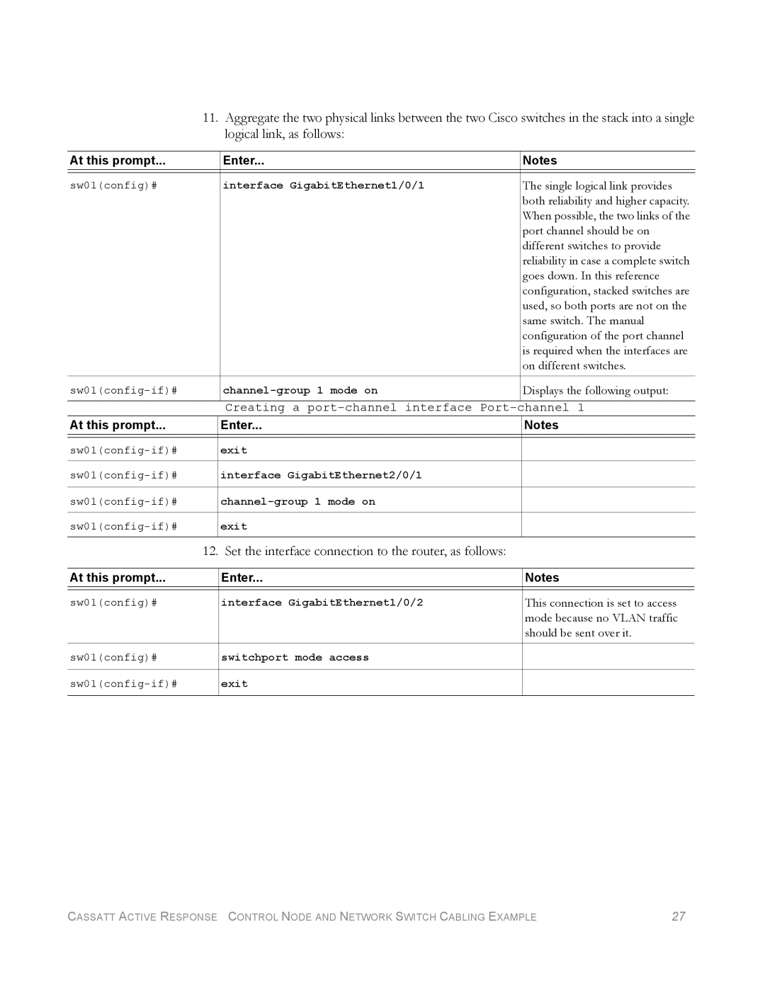
11. Aggregate the two physical links between the two Cisco switches in the stack into a single logical link, as follows:
At this prompt... |
| Enter... | Notes |
|
|
|
|
sw01(config)# |
| interface GigabitEthernet1/0/1 | The single logical link provides |
|
|
| both reliability and higher capacity. |
|
|
| When possible, the two links of the |
|
|
| port channel should be on |
|
|
| different switches to provide |
|
|
| reliability in case a complete switch |
|
|
| goes down. In this reference |
|
|
| configuration, stacked switches are |
|
|
| used, so both ports are not on the |
|
|
| same switch. The manual |
|
|
| configuration of the port channel |
|
|
| is required when the interfaces are |
|
|
| on different switches. |
|
|
|
|
| Displays the following output: | ||
|
| Creating a | channel 1 |
At this prompt... |
| Enter... | Notes |
|
|
|
|
| exit |
| |
| interface GigabitEthernet2/0/1 |
| |
|
| ||
| exit |
| |
| 12. Set the interface connection to the router, as follows: |
| |
|
|
|
|
At this prompt... |
| Enter... | Notes |
|
|
|
|
sw01(config)# |
| interface GigabitEthernet1/0/2 | This connection is set to access |
|
|
| mode because no VLAN traffic |
|
|
| should be sent over it. |
|
|
|
|
sw01(config)# |
| switchport mode access |
|
| exit |
| |
CASSATT ACTIVE RESPONSE CONTROL NODE AND NETWORK SWITCH CABLING EXAMPLE | 27 |