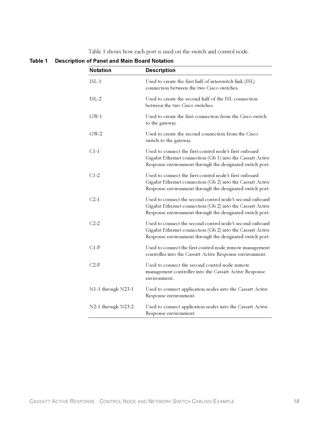
Table 1 shows how each port is used on the switch and control node.
Table 1 Description of Panel and Main Board Notation
NotationDescription
Used to create the first half of interswitch link (ISL) | |
| connection between the two Cisco switches. |
Used to create the second half of the ISL connection | |
| between the two Cisco switches. |
Used to create the first connection from the Cisco switch | |
| to the gateway. |
Used to create the second connection from the Cisco | |
| switch to the gateway. |
Used to connect the first control node’s first onboard | |
| Gigabit Ethernet connection (Gb 1) into the Cassatt Active |
| Response environment through the designated switch port. |
Used to connect the first control node’s first onboard | |
| Gigabit Ethernet connection (Gb 2) into the Cassatt Active |
| Response environment through the designated switch port. |
Used to connect the second control node’s second onboard | |
| Gigabit Ethernet connection (Gb 2) into the Cassatt Active |
| Response environment through the designated switch port. |
Used to connect the second control node’s second onboard | |
| Gigabit Ethernet connection (Gb 2) into the Cassatt Active |
| Response environment through the designated switch port. |
Used to connect the first control node remote management | |
| controller into the Cassatt Active Response environment. |
Used to connect the second control node remote | |
| management controller into the Cassatt Active Response |
| environment. |
Used to connect application nodes into the Cassatt Active | |
| Response environment. |
Used to connect application nodes into the Cassatt Active | |
| Response environment. |
|
|
CASSATT ACTIVE RESPONSE CONTROL NODE AND NETWORK SWITCH CABLING EXAMPLE | 18 |