Chapter 3 Installing and Connecting the Router

Power-Supply Modules

Power-Supply Modules

This section describes how to connect AC power and DC power to the Cisco CGR 2010 router. This section also describes how to protect the Cisco CGR 2010 router terminal block from exposure with the terminal block cover and shut off power.

Table 3-1summarizes the three power-supply modules available for the Cisco CGR 2010 router.

Table 3-1

Power-Supply Modules


Model


Description

Voltage Range


PWR-RGD-AC-DC

High-voltage AC or DC.

100-240VAC


100-250VDC


PWR-RGD-LOW-DC

Low-voltage DC.

24-60VDC 10 amps


PWR-RGD-AC-DC-C

High-voltage AC or DC.

100-240VAC


China-specific model.

100-250VDC


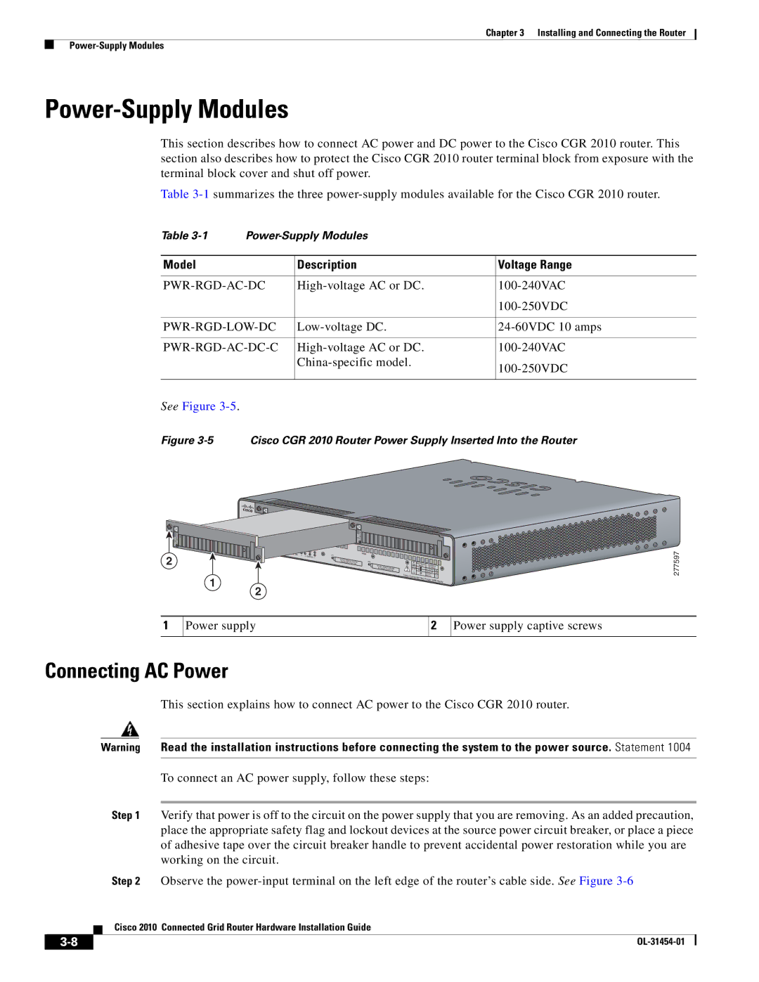
See Figure 3-5.


Figure 3-5

Cisco CGR 2010 Router Power Supply Inserted Into the Router


PSU OK PWR-150W-HV


PSUOK

PWR-150W-HV


PSUOK

HV


one power sourceunit. may have more


EN

EN

LINK

0/0


PWR-150W-


PSU1


SFP

SFP

GE


CAUTION: This


ACT

0/01

GE

SLOT


0/10

0/1


sources before

Disconnect all


than


LINK

3

1

USB

PSU


electric shock.

servicing to avoid power


CONSOLE

2

“CAUTION: This unit


SYS

SPD


may have more than

PSU2


SPD

SPD


Disconnect all power


2


SPD

2

0

CONSOLEUSB


CF1


sources before servicing toone power source.

PS

Type


1

DO


avoid electric

chock.”


Input Rating Per


CON


NOTREMOVE


LoV dc

Sources


HiV dc

24-60V


NETWORKOPE DURING


CF0

V ac,

50/60 Hz

100-270V

10A

PS

Input Terminal


RATIION


100

-240V ~

2A

Type

Input


DO


2A

Lo V


Symbol

Rating


NOTREMOVEOVE

DURING


DC

Lo


Per Source


NETWORK


Hi V DC

Hi

24 - 60 V


OPERATION


or

~

100-


10A


Cisco

2935R


V AC


250V

2A


1


Cisco

Connected

50-60 Hz

2A


Grid Router

2000 Series


2


1


Power supply


2

Power supply captive screws

Connecting AC Power

This section explains how to connect AC power to the Cisco CGR 2010 router.

277597

Warning Read the installation instructions before connecting the system to the power source. Statement 1004

To connect an AC power supply, follow these steps:

Step 1 Verify that power is off to the circuit on the power supply that you are removing. As an added precaution, place the appropriate safety flag and lockout devices at the source power circuit breaker, or place a piece of adhesive tape over the circuit breaker handle to prevent accidental power restoration while you are working on the circuit.

Step 2 Observe the power-input terminal on the left edge of the router’s cable side. See Figure 3-6

Cisco 2010 Connected Grid Router Hardware Installation Guide

3-8

OL-31454-01


Page 48
Image 48
Cisco Systems OL-31454-01 manual Power-Supply Modules, Connecting AC Power, Model Description Voltage Range

OL-31454-01 specifications

Cisco Systems OL-31454-01 refers to a specific configuration guide for Cisco networking equipment, which serves an essential role in helping IT professionals understand how to deploy and manage their networking hardware efficiently. This document is particularly relevant for those working with Cisco routers and switches, highlighting various features, technologies, and best practices in network management.

A core feature of Cisco Systems OL-31454-01 is its focus on enhancing network performance and reliability. The systems typically include advanced Quality of Service (QoS) mechanisms, ensuring that critical applications receive the necessary bandwidth and performance even during peak usage times. This is crucial for enterprises that rely on uninterrupted access to applications and services.

The guide also discusses technologies such as VLANs (Virtual Local Area Networks), which allow network administrators to segment networks for improved performance and security. By isolating traffic within different VLANs, organizations can mitigate congestion and enhance overall network efficiency.

Another critical aspect of OL-31454-01 is its in-depth look at security features. Cisco networking solutions typically come equipped with integrated security protocols, such as IPsec for Virtual Private Networks (VPNs) and advanced threat detection mechanisms. This layered approach to security helps protect sensitive data from unauthorized access and cyber threats.

Furthermore, the guide emphasizes the importance of automation and programmability in modern networks. Utilizing Cisco's software-defined networking (SDN) capabilities, network engineers can automate various tasks, reducing the potential for human error and freeing up valuable resources. The integration of tools like Cisco DNA Center provides a unified network management platform, enhancing visibility and control across the entire network.

In addition to these features, Cisco Systems OL-31454-01 outlines various compatibility options with existing technologies and infrastructure. The guide ensures that IT teams can seamlessly integrate new hardware into their current networks without significant overhauls, facilitating a more efficient transition.

Overall, OL-31454-01 serves as a comprehensive resource for deploying and managing Cisco systems, offering valuable insights into essential features, technologies, and best practices that can significantly enhance an organization's networking capabilities.