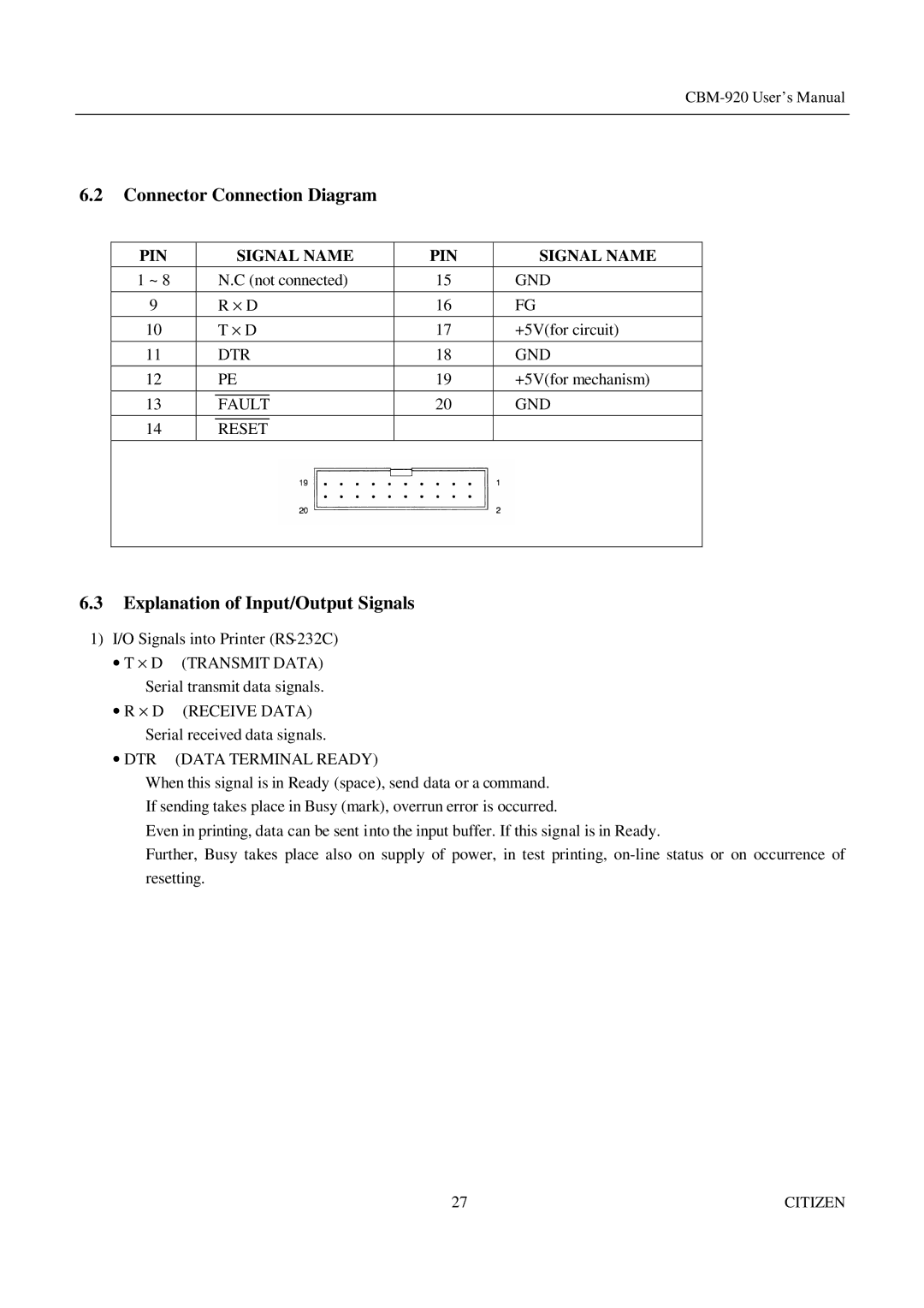
6.2Connector Connection Diagram
PIN |
| SIGNAL NAME | PIN | SIGNAL NAME | |
|
|
|
|
|
|
1 ~ 8 |
| N.C (not connected) | 15 | GND | |
|
|
|
|
|
|
9 |
| R ⋅ D | 16 | FG | |
|
|
|
|
|
|
10 |
| T ⋅ D | 17 | +5V(for circuit) | |
|
|
|
|
|
|
11 |
| DTR | 18 | GND | |
|
|
|
|
|
|
12 |
| PE | 19 | +5V(for mechanism) | |
|
|
|
|
|
|
13 |
|
| 20 | GND | |
| FAULT |
| |||
14 |
|
|
|
| |
| RESET |
|
|
| |
|
|
|
|
|
|
|
|
|
|
|
|
6.3Explanation of Input/Output Signals
1)I/O Signals into Printer
•T ⋅ D (TRANSMIT DATA) Serial transmit data signals.
•R ⋅ D (RECEIVE DATA) Serial received data signals.
• DTR (DATA TERMINAL READY)
When this signal is in Ready (space), send data or a command.
If sending takes place in Busy (mark), overrun error is occurred.
Even in printing, data can be sent into the input buffer. If this signal is in Ready.
Further, Busy takes place also on supply of power, in test printing,
27 | CITIZEN |