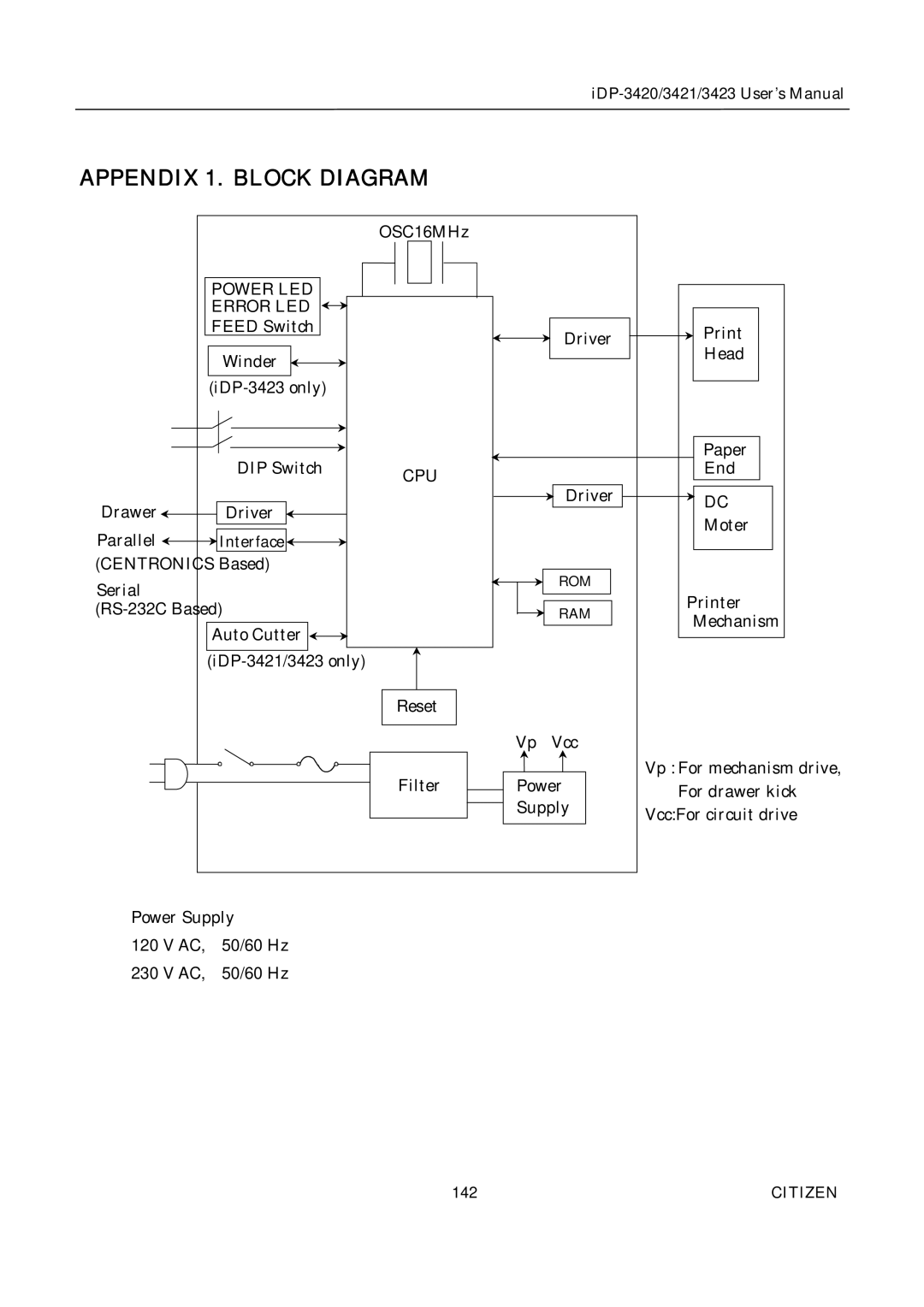
APPENDIX 1. BLOCK DIAGRAM
|
| OSC16MHz |
|
|
|
| POWER LED |
|
|
|
|
| ERROR LED |
|
|
|
|
| FEED Switch |
|
| Driver | |
|
|
|
| ||
|
|
|
| Head | |
| Winder |
|
|
| |
|
|
|
|
| |
|
|
|
|
| |
| DIP Switch |
|
|
| Paper |
| CPU |
|
| End | |
|
|
|
|
| |
Drawer | Driver |
|
| Driver | DC |
|
|
| |||
|
|
| Moter | ||
Parallel | Interface |
|
|
| |
|
|
|
| ||
(CENTRONICS Based) |
|
| ROM |
| |
Serial |
|
|
|
| |
|
|
|
| Printer | |
|
| RAM | |||
|
| Mechanism | |||
| Auto Cutter |
|
|
| |
|
|
|
|
| |
|
|
|
|
| |
|
| Reset |
|
|
|
|
|
| Vp | Vcc |
|
|
| Filter | Power | Vp : For mechanism drive, | |
|
| For drawer kick | |||
|
|
| Supply | ||
|
|
| Vcc:For circuit drive | ||
|
|
|
|
| |
Power Supply
120 V AC, | 50/60 Hz |
230 V AC, | 50/60 Hz |
142 | CITIZEN |
