6. WIRING TECHNIQUES
How to Wire This Unit
Perform the settings and | CAUTION | |
connections in the order |
| |
Throughout the process of wiring this unit, | ||
indicated by the drawing | ||
disconnect the negative | ||
below. | automobile’s battery, and leave it discon- | |
| nected until completely finished. Handling |
*Steps
pending on the component | result in dangerous electrical shock or injury |
connected. For detailed in- | if an accidental short circuit should occur. |
structions, consult the sec- |
|
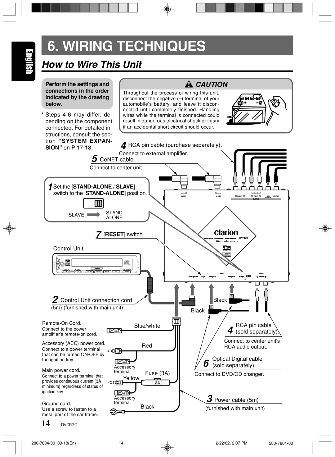
tion “SYSTEM EXPAN- | 4 RCA pin cable (purchase separately). |
SION” on P |
Connect to external amplifier. 5 CeNET cable.
Connect to center unit.
1Set the [STAND-ALONE / SLAVE]
switch to the
SLAVESTAND
ALONE
7 [RESET] switch
Control Unit
SOURCE | ADJUST | D S F | POWER |
2 Control Unit connection cord |
| |
(5m) (furnished with main unit) |
| |
Blue/white | ||
Connect to the power | ||
| ||
amplifier’s |
|
Black |
Black |
RCA pin cable
4 (sold separately).
Accessory (ACC) power cord.
Connect to a power terminal that can be turned ON/OFF by the ignition key.
Main power cord.
Connect to a power terminal that provides continuous current (3A minimum) regardless of status of ignition key.
Ground cord.
Use a screw to fasten to a metal part of the car frame.
14 DVC920
| Red |
Accessory |
|
terminal | Fuse (3A) |
Yellow | 3A |
|
Accessory terminal
Black
Connect to center unit's
RCA audio output.
Optical Digital cable
6 (sold separately).
Connect to DVD/CD changer.
3 Power cable (5m)
(furnished with main unit)
14 | 2/22/02, 2:07 PM |