Basic Operations
1. CONFIRM BEFORE OPERATION |
About the registered marks etc.
• |
frequency |
• Lt/Rt: |
sound |
• 1+1: Discrete monaural sound |
• 1/0: Front |
• 2/0: Front |
• 2/1: Front |
aural sound |
• 2/2: Front |
channel sound |
• 3/0: Front |
• 3/1: Front |
aural sound |
• 3/2: Front |
channel sound |
•STADIUM(Stadium):Large stadium without roof or walls.
•LIVE(Live):Live performance hall, larger than a jazz club.
•JAZZCLUB(Jazzclub):Jazz club with a low ceiling.
•THEATER(Theater):Movie or drama theatre.
•The original mode is resumed when the button is not pressed during a 7 second interval.
Adjusting the sound volume balance of each speaker
(AUDIO MODE)
You can adjust the sound image to suit the seat- ing position and number of passengers.
● This component has not been designed to operate as an independent unit by itself, and |
must be used in conjunction with a 5.1ch surround decoder. For information about Clarion |
center units and DVD changers that can be connected to this component, see the sec- |
tion “SYSTEM EXPANSION” on P17. Alternately, consult your retail dealer or Clarion |
service center. |
● When connecting this component (control unit), be sure to set the 5.1ch surround decoder’s |
nect the power cable. |
● In order to demonstrate optimum audio performance, be sure to change the default set- |
tings of the adjust mode’s |
|
•Manufactured under license from Dolby Labo- ratories.
“Dolby”, “Pro Logic” and
•Manufactured under license from Digital The- ater Systems, Inc. US Pat. No. 5,451,942, 5,956,674, 5,974,380, 5,978,762 and other
“DTS” and “DTS Digital Surround” are regis- tered trademarks of Digital Theater Systems, Inc. © 1996, 2000 Digital Theater Systems, Inc. All Rights Reserved.
• */*+LFE: |
• NoSIGNAL: No digital signal is input |
• |
linear PCM, Dolby digital DTS |
• Fs ERR: Current signal input has sampling |
frequency other than 32kHz, 44.1kHz, |
48kHz, or 96kHz. |
• CLIP: DSP output clipping |
Note:
•When signals are input from the ANALOG 1 con- nector or CeNET input connector, they are indi- cated by the [STEREO] display.
DSF setting
DSF (Digital Sound Field) makes it possible through sound simulation to enjoy the acoustic experience you would have in a concert hall or a live performance hall.
Any one of six sound effect patterns can be ap- plied to the sound in the signal formats DTS, Dolby Digital, or Linear PCM (or after decoding Dolby Pro Logic II signals).
• The initial setting is [DSF OFF].
1.Press the
Each time the
•The original mode is resumed when the but- ton is not pressed during a 7 second inter- val.
2.Press the [![]() ] or [
] or [![]() ] [VOL] button to adjust the value.
] [VOL] button to adjust the value.
●
The volume is adjusted in the range
●CTR (Center speaker):
Adjusts center speaker volume.
The volume is adjusted in the range
●BAL (Balance):
Adjusts the sound volume in the left and right speakers.
The sound volume is adjusted in the range L13 to R13.
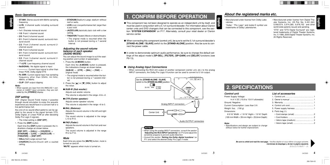
■Using Analog Input Connections
•When connecting the RCA 2ch output of another component (center unit, etc.) to the analog INPUT connectors, the Dolby Pro Logic II function can be used to convert to 5.1ch output.
Set the
SLAVE STAND
ALONE
Analog INPUT connectors
Center Unit
Audio OUTPUT connectors
2. SPECIFICATIONS
Control unit | List of accessories |
| |
Power Supply Voltage: | 1. | Control unit | 1 |
14.4 V DC (10.8 to 15.6 V allowable) | 2. | Owner’s manual | 1 |
Ground: Negative | 3. | Warranty | 1 |
Current Consumption: Less than 3 A | 4. | Control unit cord | 1 |
Weight: 5oz. (150 g) | 5. | Power supply harness | 1 |
Dimensions: | 6. | Parts bag (1) |
|
6 5/16” Width ⋅ 1 9/16” Hight ⋅ 13/16” Depth |
| • Cord clamps (small) | 2 |
(160 mm Width ⋅ 39 mm Hight ⋅ 20.6mm Depth) |
| • Cord holders | 2 |
|
| • Velcro tape (medium) | 2 |
1.Press the [DSF] button.
Each time the [DSF] button is pressed, the in- dications change as shown below.
[DSF OFF] → [HALL] → [CHURCH] → [STADIUM] → [LIVE] → [JAZZCLUB] → [THEATER] → [DSF OFF]
•HALL(Hall):Large concert hall.
•CHURCH(Church):Church with a vaulted ceiling.
●FAD (Fader):
Adjusts the sound volume in the front and rear speakers.
The sound volume is adjusted in the range R12 to F12.
Mute
Each time you press the [MUTE] button, mute is turned on and off.
“MUTE” appears when mute is turned on.
NOTES:
•When using the analog INPUT connectors, consult the section “Adjusting the RCA INPUT sensitivity” on P13 and adjust the sensitivity properly to prevent audio distortion.
•Consult the section “Setting the Dolby digital functions” on P11 and select the desired Dolby Pro Logic II mode.
Note: | • Velcro tape (small) | 2 |
•Specifications and design are subject to change without notice for further improvement.
Be sure to unfold and read the next page. / Veuillez déplier et vous référer à la page suivante. Cerciórese de desplegar y de leer la página siguiente.
8 DVC920
DVC920 | 3 | DVC920 | 4 |
2/22/02, 2:05 PM