VRX653R
Installation and Wire connection manual
■Contents
1. | BEFORE STARTING ................................................................ | 45 |
2. | PACKAGE CONTENTS ........................................................... | 45 |
3. | GENERAL CAUTIONS ............................................................ | 46 |
4. | CAUTIONS ON INSTALLATION .............................................. | 46 |
5. | INSTALLING THE MAIN UNIT ................................................. | 47 |
6. | REMOVING THE MAIN UNIT .................................................. | 49 |
7. | CAUTIONS ON WIRING .......................................................... | 49 |
8. | WIRE CONNECTION ............................................................... | 50 |
9. | SAMPLE SYSTEMS ................................................................ | 52 |
1. BEFORE STARTING
1. This set is exclusively for use in cars with a negative ground 12 V power supply.
2. Read these instructions carefully.
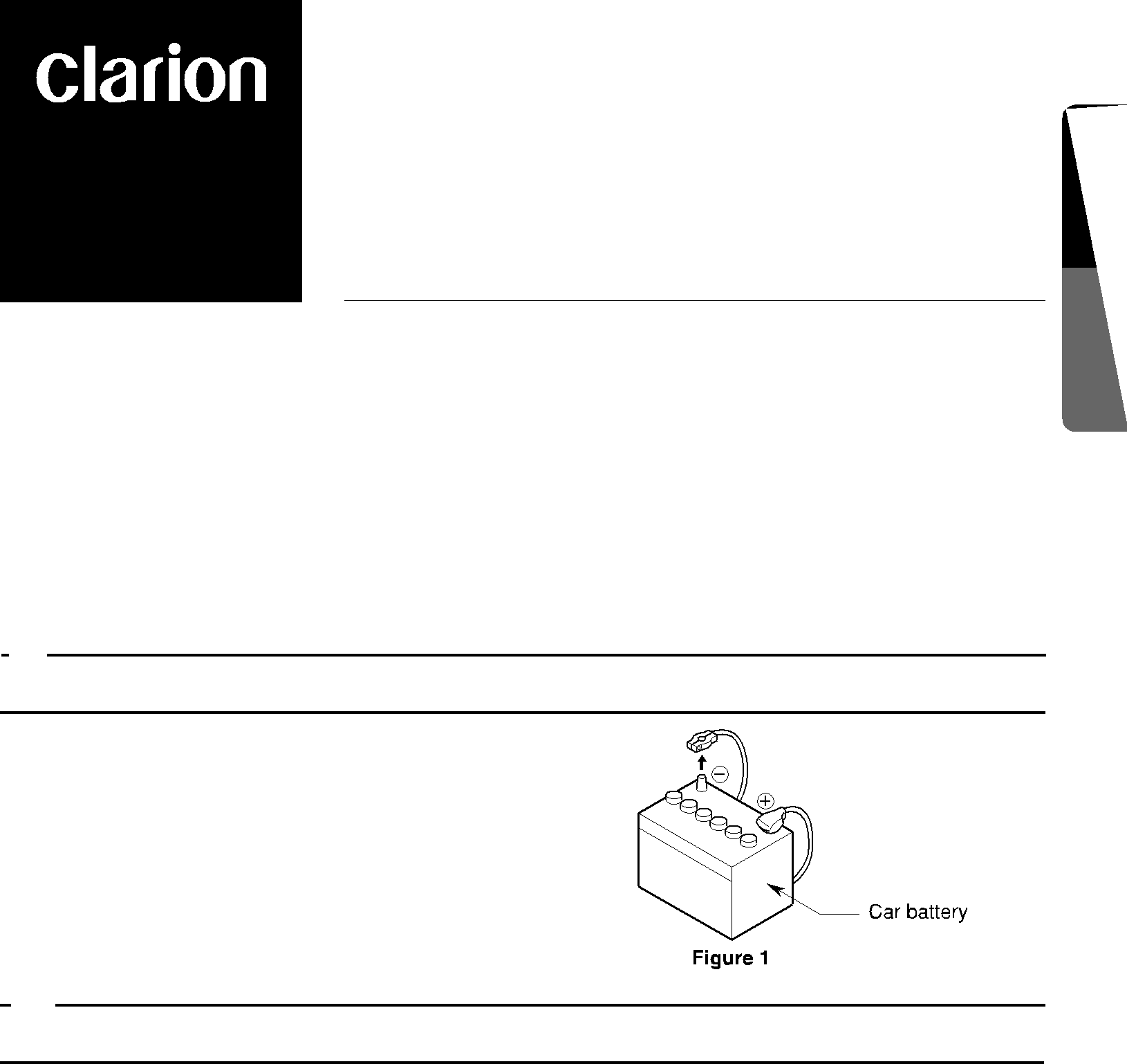
3. Be sure to disconnect the battery “ ” terminal before starting. This is to prevent short circuits during installation. (Figure 1)
English connectionmanual Installationand Wire
2. PACKAGE CONTENTS
1 | Main unit |
|
| Cord clamp |
2 | Manuals |
|
| Spacer |
| Owner’s manual & Installation manual |
|
| Special screw |
| Warranty card |
| 6 | Universal mounting bracket |
3 | Power supply lead |
| 7 | Remote control unit |
4 | Bag for accessories of the main unit (No. 1) | 8 | Battery | |
| Flat head screw (M5 ⋅ 8)............................ | 4 |
| (for remote control unit) |
| Sems hexagonal bolt (M5 ⋅ 8).................... | 5 | 9 | Outer Escutcheon |
5 | Bag for accessories of the main unit (No. 2) | 0 | DCP Case | |
| Hook plate.................................................. | 2 |
|
|
VRX653R 45