Maintenance and Service Guide
Page
Contents
Illustrated Parts Catalog
Removal and Replacement Procedures
Contents
Product Description
Features
Product Description
Resetting the Computer
Power Management
External Components
Component Function
Front Components
Right-Side Components
Rear Panel Components
Left-Side Components
Left-Side Components
Standard Keyboard Components
Fn key
Standard Keyboard Components
Top Components
Top Components
TouchPad Components
TouchPad Components
Bottom Components
Bottom Components
Design Overview
Computer Setup
Troubleshooting
Select To Do This
File Menu
Security Menu
Selecting from the Security Menu
Diagnostics Menu
Selecting from the Diagnostics Menu
System Configuration Menu
Selecting from the System Configuration Menu
Troubleshooting Flowcharts Overview
Troubleshooting Flowcharts
Flowchart No Power Part
Flowchart 2.1-Initial Troubleshooting
Flowchart 2.2-No Power, Part
Flowchart 2.3-No Power, Part
External
Flowchart 2.4-No Power, Part
Flowchart 2.5-No Power, Part
Flowchart 2.6-No Video, Part
Flowchart No Video Part
Flowchart 2.7-No Video, Part
Flowchart 2.8-Nonfunctioning Docking Device if applicable
Go to Flowchart 2.13-No OS Loading Diskette Drive
Flowchart 2.9-No Operating System OS Loading
Loading
Flowchart 2.10-No OS Loading, Hard Drive, Part
Flowchart No OS Loading Hard Drive, Part
Flowchart 2.11-No OS Loading, Hard Drive, Part
Flowchart 2.12-No OS Loading, Hard Drive, Part
Flowchart 2.13-No OS Loading, Diskette Drive
Flowchart 2.14-No OS Loading, Optical Drive
Flowchart 2.15-No Audio, Part
Flowchart 2.16-No Audio, Part
Cmos
Flowchart 2.17-Nonfunctioning Device
Flowchart 2.18-Nonfunctioning Keyboard
Pointing device Not operating Properly Connect computer
Flowchart 2.19-Nonfunctioning Pointing Device
Flowchart 2.20-No Network/Modem Connection
Serial Number Location
Illustrated Parts Catalog
Computer Major Components
Spare Parts Computer Major Components
Switch cover
Item Description Number
Keyboards
Computer Major Components
ExpressCard assembly
PC Card assembly
Spare Part
Description Number Cable Kit
Computer Major Components
Bracket Kit 407821-001
Item Description Number Plastics Kit 407779-001
System board
Computer Major Components
Description Number
Fan assembly
Thermal paste
Speakers
Computer Major Components
Mini PCI communications modules
Description Number Memory modules, 1-DIMM SD Memory Cards
Display Assembly Subcomponents
Description Display Plastics Kit
Wireless Antenna Kit includes cable
Display Hinge Kit
Display inverter board
Plastics Kit Spare Part Number Information
Plastics Kit
Cable Kit Spare Part Number Information
Cable Kit
Item Description Number Cable Kit 407775-001
Mass Storage Devices
USB digital drive not illustrated
Mass Storage Devices Spare Part Number Information
Miscellaneous Not Illustrated Spare Part Information
Miscellaneous Not Illustrated
Description Number Power cords
Sequential Part Number Listing
Sequential Part Number Listing
Spare Part Number Description
Sequential Part Number Listing
Sequential Part Number Listing
412175-001 DVB-T TV tuner
Sequential Part Number Listing
Tools Required
Removal and Replacement Preliminaries
Plastic Parts
Service Considerations
Preventing Damage to Removable Drives
Preventing Electrostatic Damage
Packaging and Transporting Precautions
Use the following grounding precautions at workstations
Workstation Precautions
Grounding Equipment and Methods
Static-Shielding Materials
Typical Electrostatic Voltage Levels
Relative Humidity Event 10% 40% 55%
Material Use Voltage Protection Level
Removal and Replacement Procedures
Serial Number
Disassembly Sequence Chart
Disassembly Sequence Chart
# of Screws Removed
Optical Drive
Battery Spare Part Number Information
Preparing the Computer for Disassembly
Reverse the above procedure to install the battery
Hard Drive Spare Part Number Information
Hard Drive
Removing the Hard Drive Cover
Removing the Hard Drive
Removing the Hard Drive Frame
Computer Feet
Memory Module Spare Part Number Information
Memory Module
Removing the Memory/Mini PCI Module Compartment Cover
Removing the Memory Shield
Reverse the above procedure to install a memory module
Mini PCI Communications Module Spare Part Number Information
Mini PCI Communications Module
Removing a Mini PCI Communications Module
RTC Battery Spare Part Number Information
RTC Battery
Optical Drive Spare Part Number Information
Optical Drive
Removing the Optical Drive
Reverse the above procedure to install an optical drive
Switch Cover Spare Part Number Information
Switch Cover
Reverse the above procedure to install the switch cover
Keyboard Spare Part Number Information
Keyboard
Releasing the Keyboard
Reverse the above procedure to install the keyboard
Display Assembly Spare Part Number Information
Display Assembly
Removal and Replacement Procedures
Disconnecting the Display and Wireless Antenna Cables
Removing the Display Assembly
Display Assembly Subcomponents Spare Part Number Information
Removing the Display Bezel Screws
Removing the Display Bezel
Disconnecting the Display Panel Cables
Removing the Display Hinge Base Covers
Removing the Display Panel and Inverter Board
Removing the Display Hinge Covers
Removing the Display Release Hook
Removing the Display Hinges
Removing the Wireless Antenna Transceivers and Cables
Base Enclosure and Top Cover Spare Part Number Information
Base Enclosure
Removal and Replacement Procedures
Removing the Base Enclosure Screws, Part
Removing the Base Enclosure Screws, Part
Reverse the above procedure to install the base enclosure
Bluetooth Module Spare Part Number Information
Bluetooth Module
Reverse the above procedure to install the Bluetooth module
System Board Spare Part Number Information
System Board
Disconnecting the LED Board Cable
Removing the Power Connector Cable
Removing the Modem Connector Cable
Removing the USB/Audio Board
Removing the System Board
Disconnecting the USB/Audio Board, Speaker, Modem Cables
Reverse the above procedure to install the system board
Display Release Button
Removing the TouchPad Cable
Removing the TouchPad Bracket
Removing the Display Release Button Components
LED Board Spare Part Number Information
LED Board
Reverse the above procedure to install the LED board
Heat Sink Spare Part Number Information
Heat Sink
Removing the Heat Sink
Reverse the above procedure to install the fan assembly
Processor Spare Part Number Information
Processor
Keyboard Section
Removing the Processor from a Socket with a Locking Screw
Reverse the above procedure to install the processor
Fan Assembly Spare Part Number Information
Fan Assembly
Removing the Fan Assembly Screw, Part
Removing the Fan Assembly Screws, Part
Removing the Fan Assembly
PC Card Assembly Spare Part Number Information
PC Card Assembly
Removing the PC Card Assembly Screws
Reverse the above procedures to install the PC Card assembly
ExpressCard Assembly Spare Part Number Information
ExpressCard Assembly
Removing the ExpressCard Assembly Screws
Removing the ExpressCard Assembly
Weight
Dimensions Metric
Input Power
Temperature
Maximum altitude unpressurized
Relative humidity noncondensing
Shock
Random Vibration
Inch, WXGA, Display
Hard Drives
80-GB 60-GB 40-GB Dimensions
DVD/CD-RW Combo Drive
Audio output
Access time
Level Cache buffer Data transfer rate
Startup time
DVD-RW
DVD±RW and CD-RW Double-Layer Combo Drive
DVD
Hardware IRQ System Function
System Interrupts
IRQ11
Address hex
System I/O Addresses
16F Unused
VGA
Size Memory Address System Function
System Memory Map
Hardware DMA System Function
System DMA
Table A-1 Phillips PM3.0×4.0 Screw
Color Qty Length Thread Width Black Where used
Head
Head Color Qty. Length Thread Width
Table A-2 Phillips PM2.5×5.0 Captive Screw
Table A-3 Black Phillips PM2.5×4.0 Screw
Table A-4 Phillips PM2.5×5.0 Screw
Phillips PM2.5×5.0 Screw Locations
Table A-4 Phillips PM2.5×5.0 Screw
Table A-4 Phillips PM2.5×5.0 Screw
Table A-4 Phillips PM2.5×5.0 Screw
Table A-4 Phillips PM2.5×5.0 Screw
Table A-4 Phillips PM2.5×5.0 Screw
Table A-4 Phillips PM2.5×5.0 Screw
Table A-4 Phillips PM2.5×5.0 Screw
Table A-4 Phillips PM2.5×5.0 Screw
Table A-4 Phillips PM2.5×5.0 Screw
Table A-5 Phillips PM2.0×3.0 Screw
Color Qty Length Thread Width Silver Where used
Table A-6 Phillips PM2.0×4.0 Screw
Phillips PM2.0×4.0 Screw Location
Table A-6 Phillips PM2.0×4.0 Screw
Table A-6 Phillips PM2.0×4.0 Screw
Table A-7 Phillips PM2.5×13.0 Screw
Color Qty Length Thread Width Black 13.0 mm Where used
Table A-7 Phillips PM2.5×13.0 Screw
Table A-7 Phillips PM2.5×13.0 Screw
Table A-8 Phillips PM2.5×9.0 Screw
Table A-9 Phillips PM2.5×7.0 Screw
Table A-9 Phillips PM2.5×7.0 Screw
Table A-10 Phillips PM1.5×3.0 Screw
Table A-11 Silver Phillips PM2.5×4.0 Screw
Silver Phillips PM2.5×4.0 Screw Location
Table A-12 Slotted SM1.5×9.0 Screw
Table A-13 Phillips PM3.0×6.0 Screw
Updating Software
Software Update Recovery
Updating the Bios
Software Update and Recovery
Updating Software Programs and Drivers
Recovering System Information
Backing Up Your Information
Using System Restore Points
Restore to a Previous Date and Time
Creating Recovery Discs
Software Update and Recovery
Reinstalling Preinstalled Programs and Drivers
Reinstalling Software Programs and Drivers
Reinstalling Programs from Discs
Performing a Recovery
Recovering from the Recovery Discs
Select Start All Programs System Recovery PC Recovery
Deleting the Recovery Partition on the Hard Drive
» Select Start Help and Support
Updating Reinstalled Software
Display Component Recycling
Display Component Recycling
Removing the Display Bezel Screw Covers and Screws
Removing the Display Bezel
Removing the Display Inverter Board
Removing the LCD Panel
Removing the LCD Panel Frame Screws
Removing the LCD Panel Frame
Removing the Backlight Cover
Releasing the Backlight Cables
Removing the Backlight Frame
Slide the backlight out of the backlight frame
Releasing the LCD Panel
Remove the LCD panel
Table D-1 Universal Serial Bus
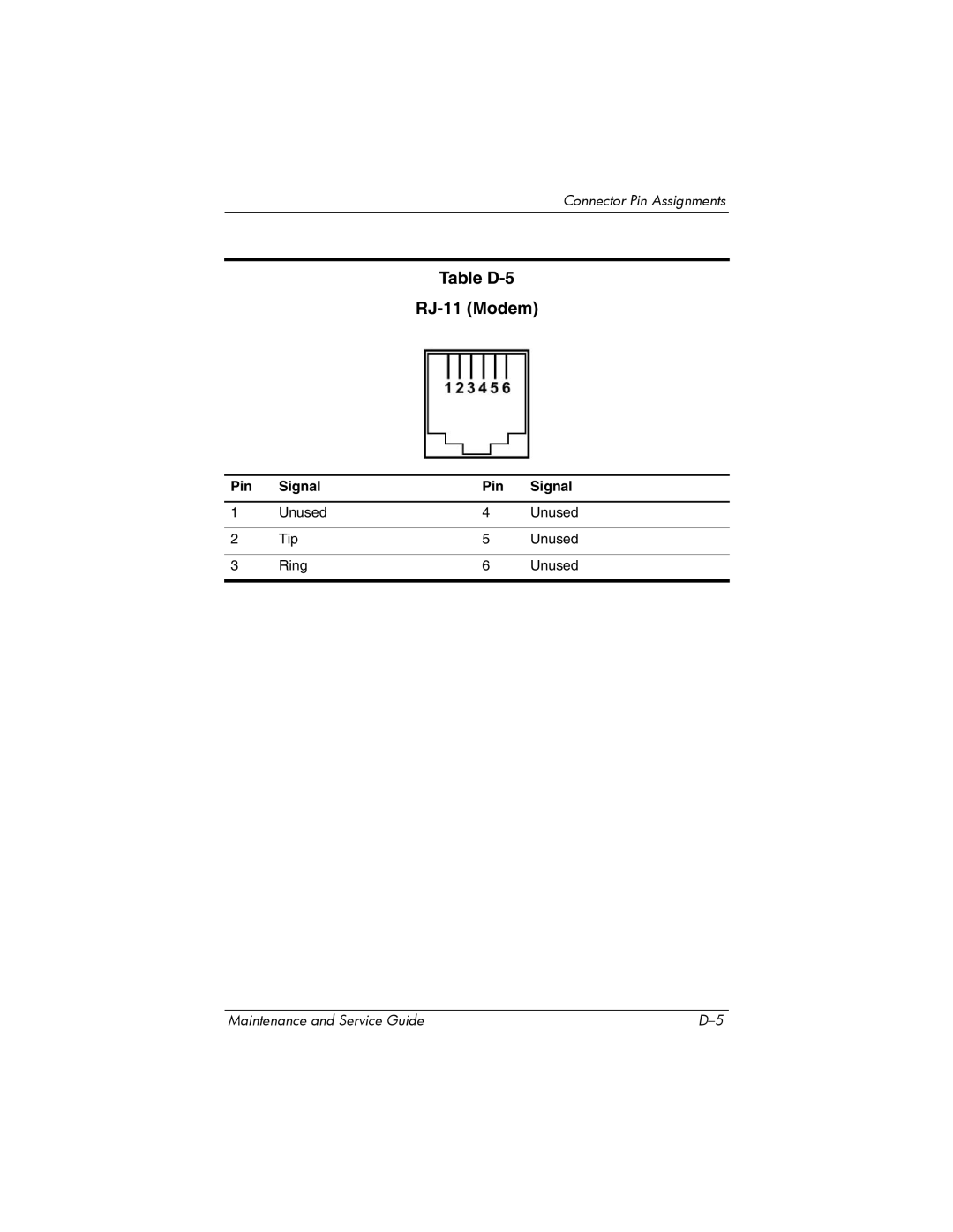
Pin Signal
Table D-2 RJ-45 Network
Table D-3 Video-Out
Table D-4 External Monitor
Table D-5 RJ-11 Modem
Table D-7 Audio-Out Headphone
Table D-6 Audio-In Microphone
Conductor Power Cord Set
Power Cord Set Requirements
General Requirements
Country-Specific Requirements
Conductor Power Cord Set Requirements
Country/Region Accredited Agency Applicable Note Number
Kema
Index
Index
Index-3
Index-4
Troubleshooting 2-14,2-23num lock key
Index-6
Index-7
Index-8