Maintenance and Service Guide
Compaq ProLiant ML350 Generation 3 Server
Page
Contents
Chapter Diagnostic Tools
About This Guide
Symbols in Text
Important Safety Information
Compaq Technician Notes
Telephone Numbers
Where to Go for Additional Help
Integrated Management Log
Text Conventions
Illustrated Parts Catalog
Mechanical Parts Exploded View
Mechanical parts exploded view
Description Spare Part Number Chassis
Mechanical Spare Parts List
Mechanical Spare Parts List
System Components Exploded View
System components exploded view
System Components Spare Parts List
System Components Spare Parts List
Description Spare Part Number Miscellaneous
Removal and Replacement Procedures
Electrostatic Discharge Information
Symbols on Equipment
Non-Hot-Pluggable Device
Preparation Procedures
Powering Down the Server
Rack Stability Warning
Bezel Door Tower Model Only
To replace the bezel door, reverse steps 3
Access Panel
To replace the access panel, reverse steps 2 through
Bezel Rack Model Only
Loosening the access panel thumbscrews
Pull the bezel up and away from the chassis
To replace the bezel, reverse steps 2 through
Removable Media Device Blank
To replace the media device blank, reverse steps 2 through
Cable Routing Diagrams
Diskette Drive Signal Cable
Item Description
IDE CD-ROM Drive Signal Cable
Removable Media Device Cable
Scsi Point-to-Point Cable
11 Scsi LVD Point-to-Point cable routing
Air Baffle
To replace the air baffle, reverse steps 2 through
13 Disconnecting the fan cables from the system board
System Fan Modules
14 Removing the system CPU fan module
15 Removing the system I/O fan module
Drive Bay Configuration
Description
Hot-Plug Hard Drive Blank
To replace a hot-plug hard drive blank, reverse steps 1
Hot-Plug Hard Drive
18 Removing a hot-plug hard drive
19 Disconnecting cables from the hot-plug hard drive cage
Hot-Plug Hard Drive Cage
20 Removing a hot-plug hard drive cage
21 Disconnecting the removable media device cables
Removable Media Device
22 Removing the removable media device
Expansion Slots
Slot Slot Number
Expansion Board
24 Removing the expansion board retainer
To replace an expansion board, reverse steps 2 through
25 Removing the expansion board
Memory Module Guidelines
26 DDR Sdram Dimm sockets location
Memory Modules
To replace a memory module, reverse steps 2 through
Processors and Processor Power Modules
Processor
29 Releasing the processor-cage latch
Rotate the processor cage upward
Rotate the processor-locking lever to release the processor
Remove the processor/heatsink assembly from the socket
To replace the processor, reverse steps 2 through
Processor Power Module
To replace a PPM, reverse steps 2 through
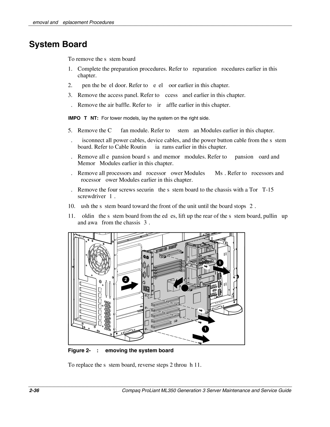
System Board
To replace the system board, reverse steps 2 through
System Battery
System Board Battery
35 Locating and removing a system board battery
To replace the power supply, reverse steps 1 through
Power Supply
To remove the power supply
Power Supply Backplane Board
37 Removing the power supply backplane board
Feet Tower Model Only
To replace the feet, reverse steps 2 through
Diagnostic Tools
Diagnostic Tools
Diagnostic Tools Utility Overview
Tool Description How to run it
Diagnostic Tools
Diagnostic Tools
For More Information
Inspect
Connectors, Switches, and LEDs
Connectors and Components
Rear Panel Components
System Board Components
System board components System Board Components
Switches
System Configuration Switch Settings
Position Default Function/Description
System ID Switch Settings
Default Position Function Description Settings
Resetting System Configuration Settings
LEDs
External health Internal health
UID
Description Status
UID LED
NIC LED
System Board LEDs
System board LEDs System Board LEDs
System Board LEDs
Hot-Plug Hard Drive LEDs
Hot-plug hard drive LEDs
Do not remove the drive. Removing a
Activity Online Fault Meaning
Hot-Plug Scsi Hard Drive LED Combinations
Drive during this process causes data
Details, provided that the array is
Network Interface Controller LEDs
Description Status Condition
Physical and Operating Specifications
System Unit Specifications
System Unit
Rack Server System Unit
Rack Server System Unit Specifications
Feature International Units English Units
Memory
Memory Specifications
1.44-M Diskette Drive Specifications
MB Diskette Drive
IDE CD-ROM Drive Specifications
IDE CD-ROM Drive
Wide Ultra3 Scsi Hot-Plug Hard Drives
Integrated Compaq NC7760 Gigabit Server Auto-switching NIC
Wide Ultra3 Scsi Hard Drive Specifications
GB Drive
Integrated Dual Channel Wide Ultra3 Scsi Adapter
Remote Insight Lights-Out Edition II Option Board
Index
Index-2
PPM
See Rbsu
Index-5
Index-6

