Connect Tech
The
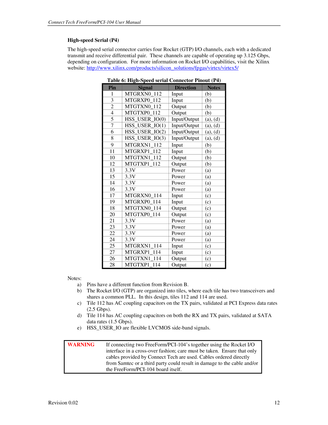
Table 6:
Pin | Signal | Direction | Notes |
1 | MTGRXN0_112 | Input | (b) |
3 | MTGRXP0_112 | Input | (b) |
2 | MTGTXN0_112 | Output | (b) |
4 | MTGTXP0_112 | Output | (b) |
5 | HSS_USER_IO(0) | Input/Output | (a), (d) |
7 | HSS_USER_IO(1) | Input/Output | (a), (d) |
6 | HSS_USER_IO(2) | Input/Output | (a), (d) |
8 | HSS_USER_IO(3) | Input/Output | (a), (d) |
|
|
|
|
9 | MTGRXN1_112 | Input | (b) |
11 | MTGRXP1_112 | Input | (b) |
10 | MTGTXN1_112 | Output | (b) |
12 | MTGTXP1_112 | Output | (b) |
13 | 3.3V | Power | (a) |
15 | 3.3V | Power | (a) |
14 | 3.3V | Power | (a) |
16 | 3.3V | Power | (a) |
17 | MTGRXN0_114 | Input | (c) |
19 | MTGRXP0_114 | Input | (c) |
18 | MTGTXN0_114 | Output | (c) |
20 | MTGTXP0_114 | Output | (c) |
21 | 3.3V | Power | (a) |
23 | 3.3V | Power | (a) |
22 | 3.3V | Power | (a) |
24 | 3.3V | Power | (a) |
25 | MTGRXN1_114 | Input | (c) |
27 | MTGRXP1_114 | Input | (c) |
26 | MTGTXN1_114 | Output | (c) |
28 | MTGTXP1_114 | Output | (c) |
Notes:
a)Pins have a different function from Revision B.
b)The Rocket I/O (GTP) are organized into tiles, where each tile has two transceivers and shares a common PLL. In this design, tiles 112 and 114 are used.
c)Tile 112 has AC coupling capacitors on the TX pairs, validated at PCI Express data rates (2.5 Gbps).
d)Tile 114 has AC coupling capacitors on both the RX and TX pairs, validated at SATA data rates (1.5 Gbps).
e)HSS_USER_IO are flexible LVCMOS
WARNING If connecting two
Revision 0.02 | 12 |
