Manuals
/
Craftsman
/
Power Tools
/
Welder
Craftsman
117.205710
operating instructions
Electrical Diagram, Circuit Diagram
Models:
117.205710
1
22
68
68
Download
68 pages
27.09 Kb
19
20
21
22
23
24
25
26
Troubleshooting
Specs
Poor Weld Bead Characteristics
Install
Parts list
Electrical Diagram
Symbol Usage
Threading Welding Wire
Setting Gun Polarity
Safety
Page 22
Image 22
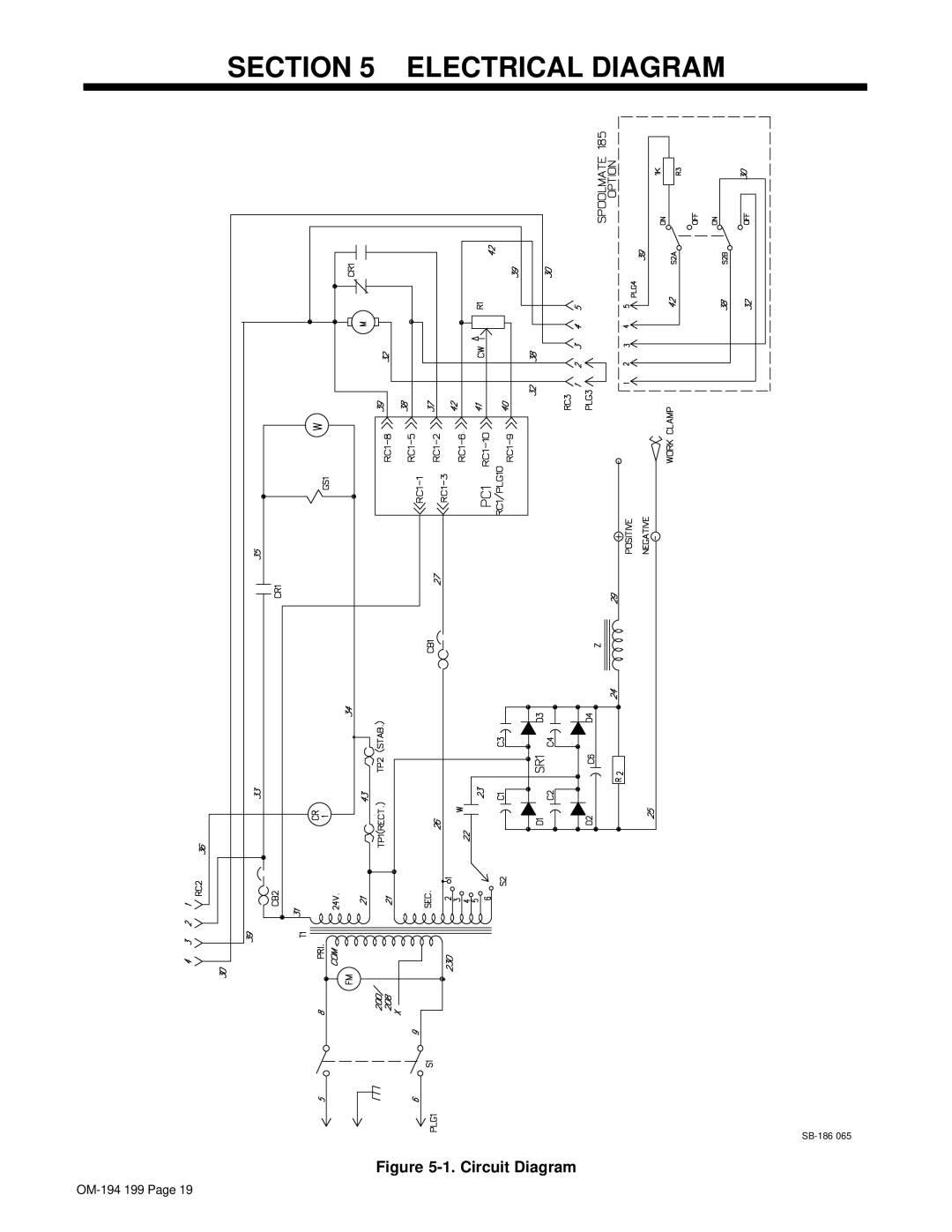
SECTION 5 – ELECTRICAL DIAGRAM
SB-186
065
Figure
5-1.
Circuit Diagram
OM-194
199 Page 19
Page 21
Page 23
Page 22
Image 22
Page 21
Page 23
Contents
MIG Welder
Owner’s Record
Table of Contents
Arc Welding Hazards
Symbol Usage
Marks a special safety message
OM-194 199
ARC Rays can burn eyes and skin
Principal Safety Standards
Fire or Explosion hazard
EMF Information
About Pacemakers
Specifications
Installation
Volt-Ampere Curves
Welding Gun Duty Cycle And Overheating
Welding Power Source Duty Cycle And Overheating
Exceeding duty cycle can damage unit and void warranty
Overheating
Installing Work Clamp
Installing Gas Supply
Polarity Changeover Label
Installing Welding Gun
Setting Gun Polarity
Tools Needed 11/16
Reinstall wrapper Tools Needed 7/16
Installing Wire Spool And Adjusting Hub Tension
Turn Off unit, and disconnect input power
Changing Input Voltage
Input Voltage
Electrical Service Guide
Selecting a Location And Connecting Input Power
Min Grounding Conductor Size In AWG/Kcmil
Threading Welding Wire
Weld Parameter
12 ga 14 ga 16 ga 18 ga 20 ga 22 ga
Shielding Gas Diameter
Wire Type
Aluminum Weld Parameter For Use With Optional Spool Gun
9.5 mm
Front Panel Controls
Operation
Controls For Standard Units
Routine Maintenance
Maintenance & Troubleshooting
Months
Head Tube Remove nozzle, contact tip, and adapter
Cleaning Or Replacing Gun Liner
Disconnect gun first
Blow out gun casing Remove liner
Replacing Switch And/Or Head Tube
Remove handle locking nut Slide handle
Replacing Gun Contact Tip
Troubleshooting
See Section
Electrical Diagram
Circuit Diagram
Typical MIG Process Connections
Wire Feeder Power Source Gun Work Clamp Workpiece
MIG Welding Gmaw Guidelines
Shielding Gas Regulator/ Flowmeter
Select Wire Size
Typical MIG Process Control Settings
Wire Recommendation Wire Speed
Based on 1/8 in material thickness Ipm = inch per minute
Holding And Positioning Welding Gun
Short Normal Long
Conditions That Affect Weld Bead Shape
Push PerpendicularDrag
ShortNormalLong
Good Weld Bead Characteristics
Poor Weld Bead Characteristics
Gun Movement During Welding
Troubleshooting Excessive Penetration
Troubleshooting Excessive Spatter
Troubleshooting Porosity
Possible Causes Corrective Actions
Troubleshooting Incomplete Fusion
Troubleshooting Lack Of Penetration
Troubleshooting Burn-Through
Troubleshooting Distortion
Troubleshooting Waviness Of Bead
Weld bead
Application
Common MIG Shielding Gases
Flat & Horizontal1 Fillet
Parts LIST-Welder Model No
Parts List-Welder Model No
Center Baffle w/Components
083
M-15 Gun -1 Item
Includes Items
23 15
OM-194 199
Efectiva 1 enero
OM-194 199 Página
Indice
Peligros en Soldadura de Arco
Uso de Símbolos
Anota un mensaje especial de seguridad
LOS Rayos DEL Arco pueden que- mar sus ojos y piel
Está ndares Principales de Seguridad
Peligro de Fuego O Explosion
Informació n del EMF
Acerca de Marcadores de Paso
Especificaciones
Seccion 9 Instalacion
Curvas Voltio-Amperio
Sobrecalentando
Ciclo de trabajo de la antorcha y el sobrecalentamiento
Definició n
Instalando la Grampa de Trabajo
Instalando el Gas Protectivo
Instalando la Pistola Fijando la Polaridad de la Pistola
Herramientas Necesarias 11/16 pulg OM-194 199 Página
Cambiando el Voltaje de Entrada
No mueva o opere la unidad donde podría voltearse
11. Guía de Servicio Elé ctrico
Lo 511 o CEC Secció n
Pulg 150 mm Abra el ensamblaje de presión
Enhilando el Alambre de Soldadura
Apriete
Del
Pará metro de Soldadura
Tipo de Diá metro
Flujo
100% Argón
Tipo de Alambre Diá metro del Grosor del Material
100 OM-194 199 Página
Controles para las Unidades Es- tá ndar
Seccion 10 Operacion
Controles del Panel Frontal
Control de Alimentación de Alambre
11-2. Bré iquers CB1 y CB2
Seccion 11 Mantenimiento Y Correccion DE Averias
Mantenció n Rutinario
Instalando los Rodillo de Alimentació n y Guía de Alambre
Seccion 12 Diagramas Electricos
Seccion 13 Directivas Para Soldadura MIG Gmaw
Conexiones Típicas para el Proceso MIG
Alambre
Fijaciones de Control para un Proceso de MIG Típico
Gama de Amperaje
Seleccione el Tamañ o del Alambre
Como Sostener y Posicionar la Pistola de Soldar
Perpendicular Arrastre
Condiciones que Afectan la Forma del Cordó n de Suelda
Empuje
Corto Normal
Características Malas de un Cordó n de Soldadura
Movimiento de la Pistola durante la Suelda
Características Buenas de un Cordó n de Soldadura
Soluciones a Problemas de Soldadura Porosidad
Soluciones a Problemas de Soldadura Excesiva Salpicadura
Causas Posibles Acció n Correctiva
Soluciones a Problemas de Soldadura Falta de Penetració n
Soluciones a Problemas de Soldadura Penetració n Excesiva
Soluciones a Problemas de Soldadura Fusió n Incompleta
No cubre la unión formada por el material base
Soluciones a Problemas de Soldadura Hacer Hueco
Soluciones a Problemas de Soldadura Distorció n
Causas Posibles
Argó n + 25% CO
Gases Má s Comunes para Protecció n de Soldadura MIG
Aplicació n
Horizontales
Apuntes
OM-194 199 Página
Top
Page
Image
Contents