Unit
You must read Understand this owners
Serial No
Date Purchased
Engine
Telephone
Tableofcontents
Hazard Symbols and Meanings
Safety Alert Symboland SignalWords
DAHGER- Amputation Hazard
Control Symbols on Equipment
Operatorsafety
Readthe Manual
Discharge Chute
Fuel Handling
Operationand EquipmentSafety
Whentransportingequipment
TransportwithfueltankEMPTY,orwithfuelshut-offvalveOFE
Moving Parts
Engine Safety
Thrown Objects
Children
Maintenanceand Storage
Part Ho Shift Decal
Auger ControlDecal EngineDecals Part Ho
TractionControl Decal
ProductID Humber
Toolsrequiredforassemblycontentsof SHiPPiNGCARTON
Assembly
Unpackingthe Snowthrower Clutch Control Cables
Removethepackingmaterialfromthehandleassembly
Lowerhandle
Upper HandleAssembly CrankAssemblyFigure5
Check the Cables
Checkthe Cables
Shifter Handle
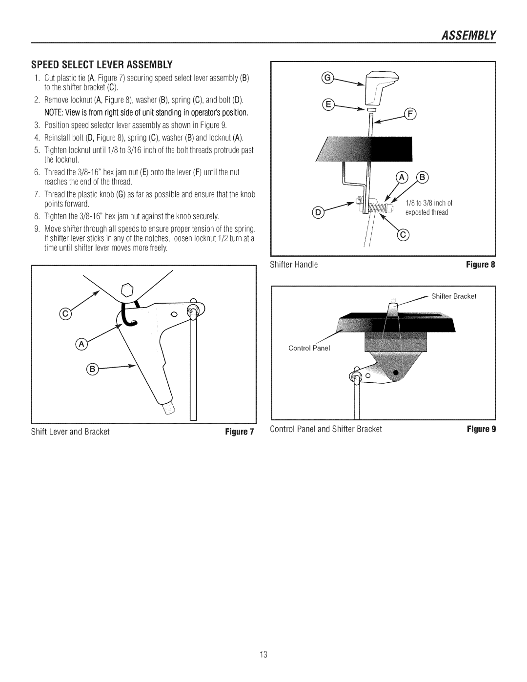
Speed Select Lever Assembly
Shift Lever and Bracket Control Paneland Shifter Bracket
HeadlightAssembly
Headlight Assembly
Removethe nutA, andIockwasherBfromthecarriage boltC
Shownin
R 1
Featuresand Controls
Snowthrowerand Enginecontrols
Snowthrowercontrols
Enginecontrols
EngineControls
UP DisengagePosition
Operatethe Snowthrower
Snow thrower is clear of bystandersor obstacles
Poor ventilated area. Engine exhaust contains Carbon
Carelessly
TRACTIONLOCKPiNS
ReleasethetractiondriveclutchleverB
Below, use a synthetic5W30 motor oil for easier starting
Power receptacle
When handling or storing gasoline. Turnengine off
Engine or significantly reducethe performance
Start the Engine
Rapidlyto avoid kickback
InsertingSafetyKey
Or a similarly qualified personto avoid a hazard
Stop the Engine
Operatingtips
Cleara Cloggeddischargechute
Checkto MakeSure AugerBladeStopsWithin SecondsAfterRight
Safety
Engine
ChuteRotationGear LubricatingAugerGearBox
EquivalentMaximum3.-1/4 ounces,92gramsshouldbeused
Full CheckCrankcaseOil Level OilDrainPlug
Maintenance
Remove the Snow Hood
ConnectingChokeControlKnob SnowThrowerEngine
Repairs or adjustments
ADJUSTSKiD Height
To adjustskids, proceed as follows
Checkand Replace Spark Plug
Auger Drive Belt
TractionDrive Belt
Tightennut
Auger Drive Cable
Checkandadjustthecables
TractionDrive Cable
TractionDriveCable CheckAdjustmentofTractionDriveCable
Any cover or guard is removed
AUGERSHEARPiN Replacement
Incorrectly
Cause an increasein air pressure resulting in an
LUBRICATEHE× Shaftand Chains
Offseasonstorage
Removefromstorage
During storage
TROUBLESHOOT/NG
Problem Lookfor
TROLIBLESHOOT/NG
Problem Lookfor Remedy
WARRANT/ES
Maintenance Agreement
Intermediate
EnginePower Rating Information
Page
PTS
RepairParts
SeeTraction DriveGroup Craftsman 27 Snowthrower C950-52943-O
Engine & Frame
Craftsman 27 Snowthrower C950-52943-0
Engine Frame
Footnotes
Traction Drive
Traction Drive
Auger Housing
16 X 3/4
Discharge Chute
Chute Assembly
Handle Assembly
Handle Upper
Chute Rod
852-7
Assembly Yoke & ROD
Control Panel
Description
Control Panel
Decals
Decals
Gear Case
QTY Description
REF no
Wheels
Wheels
623
Headlight
629 630
Footnotes PTS
742 692564
Replacement Engine
Ring
MSC000099
Assemblies include all parts shown in frames
472 791948 Knob-Choke Shaft 104 694918
694874 Gasket-Intake 137 698781 Gasket-Float
604 r 564 604A
695307 Spring Control Lever Governed Idle 562 793216 Bolt
694867 Spring-Governor 505 691251 Nut Red
694864 Lever Governor Control Control Lever
699047 Guard-Flywheel 597 691696
78 %
696710
Pawl Friction Plate
1005
792576 Wire Assembly 1119 699772 Screw
793206 Wire-Stop 1009 795012 Screw
795909 Motor-Starter 735 795901 Cord-Starter
492341 Armature-Magneto 851 692424 Terminal-Spark
Snow Hood Assemblies
391086s Seal-Oil 358 795201 Gasket
Engine Briggs & Stratton Model 20M114-O141-E1
Needle
Screw
Nut, 1/2
Wrench & Fastener Size Guide
R6vA
Manueln
07/2009
Num6ro de s6rie
Souffleuse neige Num6ro de modele
Num6ro de s6rie Dale dachal Adresse du magasin dachal
Ville
Utilisation
Sicuriti DE Lopirateur Assemblage
Entretien
Reiviisage
Renseignementset symbolesde danger
Symboledalertede scurit6 et rootsde signal
DAHGER- Risque damputatien
Lecturedu manuel
Symbolesde commandesur Yequipement
CuritSimalut,is. oumalentretenue,cecie tre
Securitedeloperateur
S6curit6de moteur
0bjets projet6s
Enfants
Resulteralamortoublessuregrave
Explosionetfeupeuenr6sulter
S6curit6du moteur suivre Efltretienet entreposage
Hlllll!ff!l,, LamiseenmarchedumoteurproduitdelachaleurLes
Arrire du carter du moteur
Commandode
4-20 x 1.75 Vis Entretoise
Couteau Souffleuseaneige Clesde1/2 pouceoudes amolette
Pommeau
Rep6rezet retirezlesacdepiecesd6tach6es
Deballage
Superieureet DELAIViANIVELLE
Montagedelapoignee
Montagede la manivelle
Poignedu slecteur devitesses
Montagedelasilecteurdevitesse
Montagedu phare
Montagede la goulotte
Fiemafique Ne pas deplacer le levier de vitesse alors que
FONCTION$ET COMMA/l/DES
Bouchondhuilede rernpiissagejauge dhuiiealiong
Commandesde moteur COlVlIVlANDESDU IVlOTEUR
Utilisationdela Souffleusea NEiGE
Leviersde commande
D6marrerlemoteurVoir. D6marrerlemoteur,, dartscettesection
Droitedelagoulotted@ection
Traction Goupille DE SURET! f
Utilisation
Arreter LA Souffleuse a Neige
REiVlARQUF Le rnoteurest iivr dusinerernpii dhuile
REIVlPLIRLE RiSERVOIRDESSENCE
UT/L/SAT/ON
DEIVlARRERLEiVIOTEUR
HEPASFUIVlERlurant le rempJissagelu rservoir. He jamais
AVERTiSSEIVlENT Si le cordonest endommag, ii dolt
UT/USAT/ON
D6cartertout danger
Moteur ne d6marre pus sansla cl de contact/scurit
Arreterlemoteur
DiGAGERUNE GOULOTTEDiJECTIONOBSTRUiE
Nettoyerlasouffleuseaneigeavecsoinapreschaqueutilisation
Usage Usage Heures Heures Heures Saison
Entretien
Neige
Moteur
Graissagede LABOiTEDENGRENAGEDEVIS
ENTRET/EN
SANSFiN
Graissagede Larbredevis SANSFiN
Vidangerihuiie
ENTRETiENDUiVIOTEUR
Changerla BOUGIEDALLUIVlAGE D6poserle capot neige
LabougieEestapresentaccessible
Rlglerla Hauteurdespatins
Rgler ou changerla bougie
Mme hauteur des deux c0ts
Courroie dentrainementde traction
AJUSTEIVlENTDESCOURROIES
Courroie dentrainementde vissansfin
AVERTISSEMENTNe pas trop serrer car ceJapeut
AJUSTEIVlENTDU Guidedecourroie
R6glage du ¢ble de commande des lames
Verifierlescbles
AVERTISSEiVlENTVidanger Jesseflce Jextrieur
Reglage du cble decorflrnandede la traction
IMPORTANT Ns pas rsmplacsrIss goupiiies ds cisaillement
Changerlesgoupillesde CISAILLEIVlENT Devis SANSFiN
CONTRgLER LES Pneus
Ns pas gonfler iss pneos-dsssusde ia prsssion
Reivusagehorssaison
Remisage
Lubrifier Larbrehexagonalet CHAiNES
Cherchezpour
Puslectrique
Ta souffleuse
PROBLFIVlE
Neige vire dunc0t6
La barre de raclage ne
Garantie limit e de Craftsman
GARANT/ES
GARAtVT/ES
Modern
Vitessesdentrainement
Inforrnations concernantla puissancethoriquedu moteur
Domicilio Para Ordenar piezas
LE-FOYER