Installation Guide
Hardware Installation
Installing the DM system into a rack
The DMTH4 occupies a single space. There are no special ventilation requirements. Mount with 4 rack screws using the appropriate mounting holes. It is recommended to use nylon washers to prevent damage to the front panel’s finish when tightening the screws.
For North American installations, connect the Power Cable supplied with the unit between the DMTH4 and a stable power source. All DM processors have internal switching power supplies that can tolerate voltages ranging from 100 VAC to 240 VAC. Use an approved power cable for installations outside North America.
Cables
It is recommented to use lacing bars for cable strain relief when mounting in a rack. Use only professional audio cable with proper shielding - typically, two con- ductor plus ground/shield.
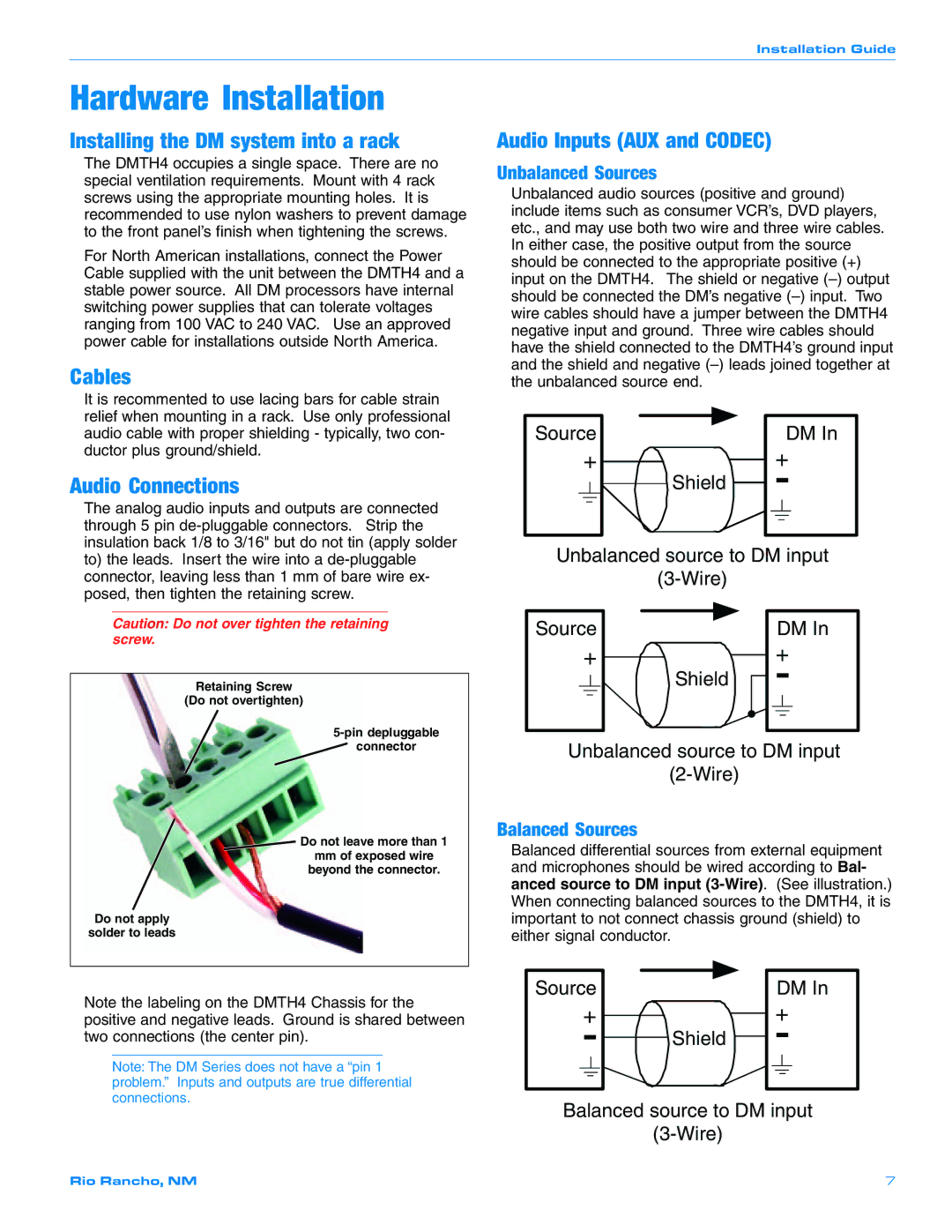
Audio Connections
The analog audio inputs and outputs are connected through 5 pin
Caution: Do not over tighten the retaining screw.
Retaining Screw
(Do not overtighten)
connector
![]() Do not leave more than 1 mm of exposed wire beyond the connector.
Do not leave more than 1 mm of exposed wire beyond the connector.
Do not apply
solder to leads
Audio Inputs (AUX and CODEC)
Unbalanced Sources
Unbalanced audio sources (positive and ground) include items such as consumer VCR’s, DVD players, etc., and may use both two wire and three wire cables. In either case, the positive output from the source should be connected to the appropriate positive (+) input on the DMTH4. The shield or negative
Source | DM In |
+ | + |
Shield | - |
Unbalanced source to DM input
Source | DM In |
+ | + |
Shield | - |
Unbalanced source to DM input
Balanced Sources
Balanced differential sources from external equipment and microphones should be wired according to Bal- anced source to DM input
Note the labeling on the DMTH4 Chassis for the positive and negative leads. Ground is shared between two connections (the center pin).
Note: The DM Series does not have a “pin 1 problem.” Inputs and outputs are true differential connections.
Source | DM In |
+ |
| + |
- | Shield | - |
|
Balanced source to DM input
Rio Rancho, NM | 7 |