DMTH4
Audio Outputs (AUX and CODEC)
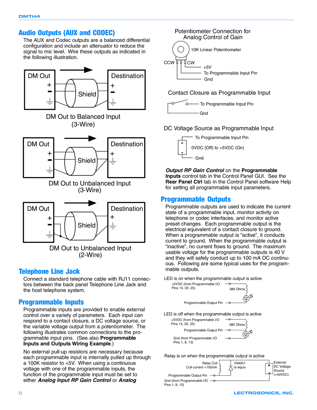
The AUX and Codec outputs are a balanced differential configuration and include an attenuator to reduce the signal to mic level. Wire these outputs as indicated in the following illustration.
DM Out | Destination |
+ | + |
- | Shield - |
DM Out to Balanced Input
(3-Wire)
Potentiometer Connection for
Analog Control of Gain
10K Linear Potentiometer
CCW CW
+5V
To Programmable Input Pin Gnd
Contact Closure as Programmable Input
To Programmable Input Pin
Gnd
DC Voltage Source as Programmable Input
DM Out
+
-
Shield |
Destination
+
![]() To Programmable Input Pin
To Programmable Input Pin
0VDC (Off) to +5VDC (On)
Gnd
Output RP Gain Control on the Programmable Inputs control tab in the Control Panel GUI. See the
DM Out to Unbalanced Input
DM Out | Destination |
+ | + |
- | Shield |
|
DM Out to Unbalanced Input
Telephone Line Jack
Connect a standard telephone cable with RJ11 connec- tors between the back panel Telephone Line Jack and the host telephone system.
Programmable Inputs
Rear Panel Ctrl tab in the Control Panel software Help for setting all programmable input parameters.
Programmable Outputs
Programmable outputs are used to indicate the current state of a programmable input, monitor activity on telephone or codec interfaces, and monitor active preset changes. Each programmable output is the electrical equivalent of a contact closure to ground. When a programmable output is “active”, it conducts current to ground. When the programmable output is “inactive”, no current flows to ground. The maximum usable voltage for the programmable outputs is 40 V and they will safely conduct up to 100 mA DC continu- ous. Following are some typical uses for the program- mable outputs.
LED is on when the programmable output is active
+5VDC (from Programmable I/O |
|
Pins 14, 20, 25) | 380 Ohms |
| |
Programmable Output Pin |
|
Programmable inputs are provided to enable external control over a variety of parameters. Each input can respond to a contact closure, a DC voltage source, or the variable voltage output from a potentiometer. The following illustrates common connections to the pro- grammable input pins. (See also Programmable
Inputs and Outputs Wiring Example.)
No external
LED is off when the programmable output is active
+5VDC (from Programmable I/O |
|
Pins 14, 20, 25) | 380 Ohms |
Programmable Output Pin |
|
Gnd (from Programmable I/O |
|
Pins 1, 8, 13) |
|
Relay is on when the programmable output is active
Relay Coil | 1N4001 |
Coil current <100mA | or equiv. |
Programmable Output Pin
Gnd (from Programmable I/O
Pins 1, 8, 13)
External DC Voltage Source (<40VDC)
8 | LECTROSONICS, INC. |
