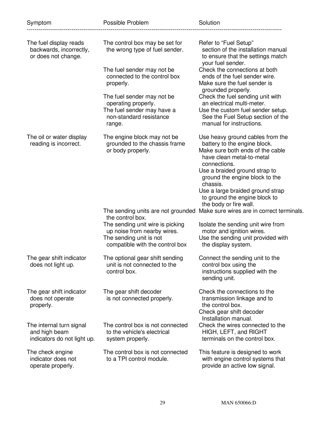
SymptomPossible ProblemSolution
The fuel display reads backwards, incorrectly, or does not change.
The oil or water display reading is incorrect.
The gear shift indicator does not light up.
The gear shift indicator does not operate properly.
The internal turn signal and high beam indicators do not light up.
The check engine indicator does not operate properly.
The control box may be set for the wrong type of fuel sender.
The fuel sender may not be connected to the control box properly.
The fuel sender may not be operating properly.
The fuel sender may have a
The engine block may not be grounded to the chassis frame or body properly.
The sending units are not grounded the control box.
The sending unit wire is picking up noise from nearby wires.
The sending unit is not compatible with the control box
The optional gear shift sending unit is not connected to the control box.
The gear shift decoder
is not connected properly.
The control box is not connected to the vehicle's electrical system properly.
The control box is not connected to a TPI control module.
Refer to “Fuel Setup”
section of the installation manual to ensure that the settings match your fuel sender.
Check the connections at both ends of the fuel sender wire.
Make sure the fuel sender is grounded properly.
Check the fuel sending unit with an electrical
Use the custom fuel sender setup. See the Fuel Setup section of the manual for instructions.
Use heavy ground cables from the battery to the engine block.
Make sure both ends of the cable have clean
Use a braided ground strap to ground the engine block to the chassis.
Use a large braided ground strap to ground the engine block to the body or fire wall.
Make sure wires are in correct terminals.
Isolate the sending unit wire from motor and ignition wires.
Use the sending unit provided with the display system.
Connect the sending unit to the control box using the instructions supplied with the sending unit.
Check the connections to the transmission linkage and to the control box.
Check gear shift decoder Installation manual.
Check the wires connected to the HIGH, LEFT, and RIGHT terminals on the control box.
This feature is designed to work with engine control systems that provide an active low signal.
29 | MAN 650066:D |