CHECK ENG (-)
The check engine terminal is used with fuel injection ECM’s to display engine problems and trouble codes. The CHECK input is activated by a ground signal from the ECM. Whenever the check input is grounded, the system will display “ENGINE” on the message display. This message can be cleared by pressing and holding switch 2.
When the ECM is placed into diagnostic mode, trouble codes can be read by counting the flashes. Consult a service manual for the fuel injection system that you have for further information on trouble codes.
With some ECM’s, a 12 volt light bulb may need to be connected in addition to the CHECK input in order to provide proper current loading. In this case, both the bulb and our display system indicator would come on when the check engine wire is “active”.
AUX. I/O
This jack is used to connect future bus expansion modules (BIM). Do not attempt to plug in any other device to this jack or damage to the control box will occur. This connector should be left open, unless using a Dakota Digital product designed for it. Operation is discussed with BIM units purchased separately.
DISPLAY RIBBON CABLE
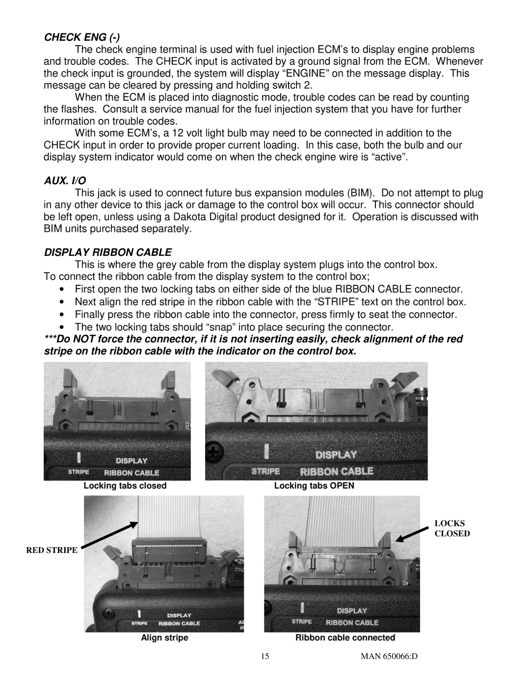
This is where the grey cable from the display system plugs into the control box. To connect the ribbon cable from the display system to the control box;
∙First open the two locking tabs on either side of the blue RIBBON CABLE connector.
∙Next align the red stripe in the ribbon cable with the “STRIPE” text on the control box.
∙Finally press the ribbon cable into the connector, press firmly to seat the connector.
∙The two locking tabs should “snap” into place securing the connector.
***Do NOT force the connector, if it is not inserting easily, check alignment of the red stripe on the ribbon cable with the indicator on the control box.
Locking tabs closed | Locking tabs OPEN |
LOCKS
CLOSED
RED STRIPE
Align stripe | Ribbon cable connected |
15 | MAN 650066:D |