CONTROL BOX MOUNTING
Once the display panel is in place, mount the control box within reach of the ribbon cable on the display panel (approximately 3 feet). Pick a mounting location that will allow you access to wire all of the inputs on the control box. Double sided tape, hook and loop fasteners, or screws in the two tabs on the case work fine for securing the control box under the dash.
When selecting a mounting location, avoid placing the control module next to, or just opposite of the firewall, from ignition components, ie: Ignition coil, HEI, etc. Ignition components can emit tremendous amounts of electric noise, affecting the operation of electrical components.
Wiring the control box into the vehicle
While the control box contains several connections, the wiring is straightforward. Depending on how many auxiliary functions you want displayed, not every terminal will be used in most applications. Below we describe the function of each terminal, what they do, and how to wire them.
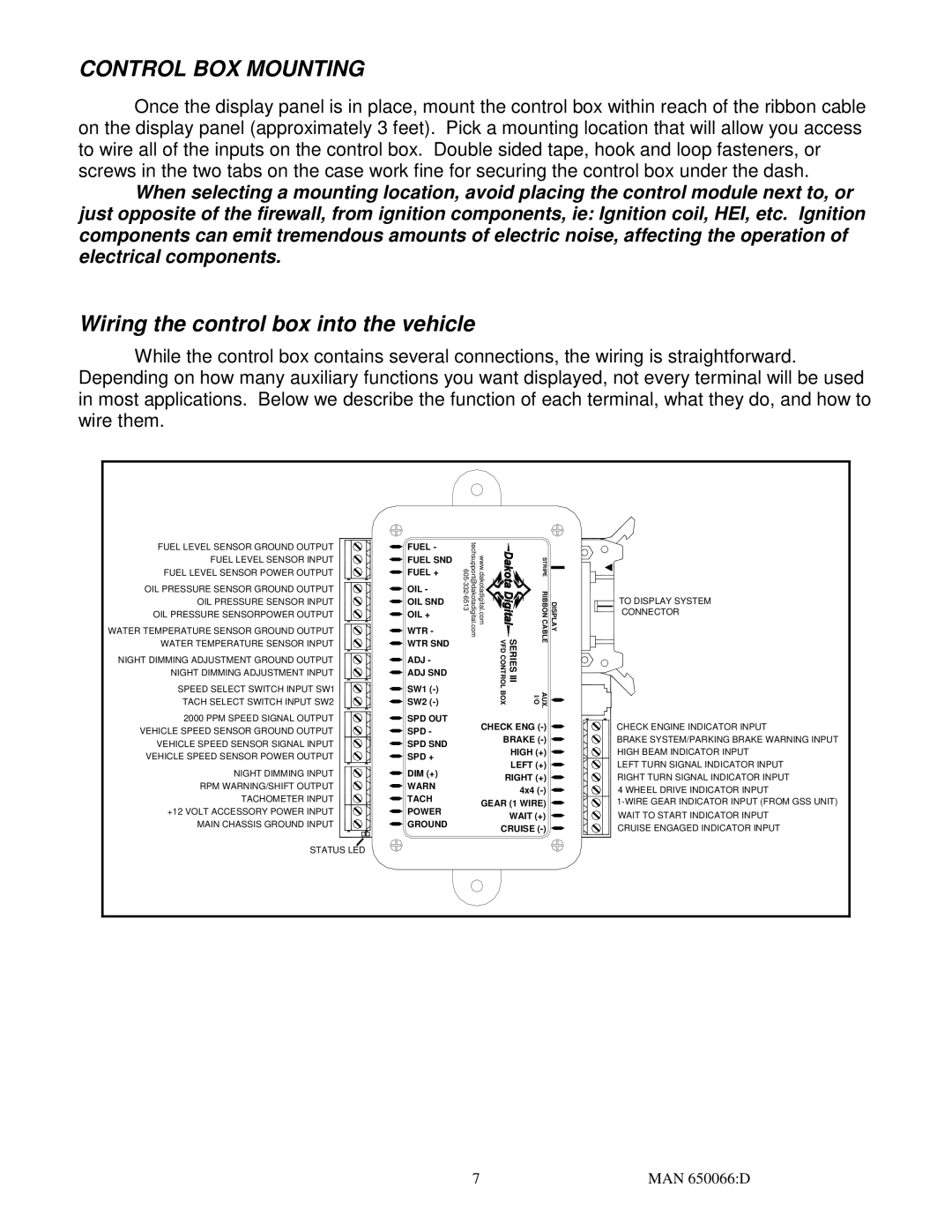
FUEL LEVEL SENSOR GROUND OUTPUT FUEL LEVEL SENSOR INPUT FUEL LEVEL SENSOR POWER OUTPUT
OIL PRESSURE SENSOR GROUND OUTPUT OIL PRESSURE SENSOR INPUT OIL PRESSURE SENSORPOWER OUTPUT
WATER TEMPERATURE SENSOR GROUND OUTPUT WATER TEMPERATURE SENSOR INPUT
NIGHT DIMMING ADJUSTMENT GROUND OUTPUT NIGHT DIMMING ADJUSTMENT INPUT
SPEED SELECT SWITCH INPUT SW1
TACH SELECT SWITCH INPUT SW2
2000 PPM SPEED SIGNAL OUTPUT VEHICLE SPEED SENSOR GROUND OUTPUT VEHICLE SPEED SENSOR SIGNAL INPUT VEHICLE SPEED SENSOR POWER OUTPUT
NIGHT DIMMING INPUT RPM WARNING/SHIFT OUTPUT TACHOMETER INPUT +12 VOLT ACCESSORY POWER INPUT
MAIN CHASSIS GROUND INPUT
FUEL -
FUEL SND FUEL +
OIL -
OIL SND OIL +
WTR -
WTR SND
ADJ -
ADJ SND
SW1
SW2
SPD OUT SPD -
SPD SND SPD +
DIM (+)
WARN
TACH POWER GROUND
www.dakotadigital.com techsupport@dakotadigital.com | VFD CONTROL | SERIES III | STRIPE RIBBON CABLE |
| BOX |
| AUX. I/O |
CHECK ENG
HIGH (+)
LEFT (+)
RIGHT (+) 4x4
GEAR (1 WIRE) WAIT (+)
CRUISE (-)
DISPLAY
TO DISPLAY SYSTEM
CONNECTOR
CHECK ENGINE INDICATOR INPUT
BRAKE SYSTEM/PARKING BRAKE WARNING INPUT HIGH BEAM INDICATOR INPUT
LEFT TURN SIGNAL INDICATOR INPUT RIGHT TURN SIGNAL INDICATOR INPUT 4 WHEEL DRIVE INDICATOR INPUT
CRUISE ENGAGED INDICATOR INPUT
STATUS LED
7 | MAN 650066:D |