The keyboard connector may have a label on it that shows the correct orientation of the keyboard connector to the
3.Carefully turn the keyboard over. Align the keyboard boss support, fit the left side of the keyboard into place, and then snap the right side of the keyboard into place.
NOTICE: Position the keyboard flex and track stick cables so that they are not pinched when you replace the keyboard in the bottom case.
4.Check that the keyboard is correctly installed. The keys should be flush with the left and right surfaces of the palm rest.
5.Replace the center control cover, close the display assembly, and turn the computer over.
6.Reinstall the five M2.5 x
Display Assembly
NOTICE: You must remove the display assembly before you remove the palm rest.
NOTICE: Disconnect the computer and any attached devices from electrical outlets, and remove any installed batteries.
NOTICE: To avoid ESD, ground yourself by using a wrist grounding strap or by touching an unpainted metal surface on the computer.
NOTICE: Read "Preparing to Work Inside the Computer" before performing the following procedure.
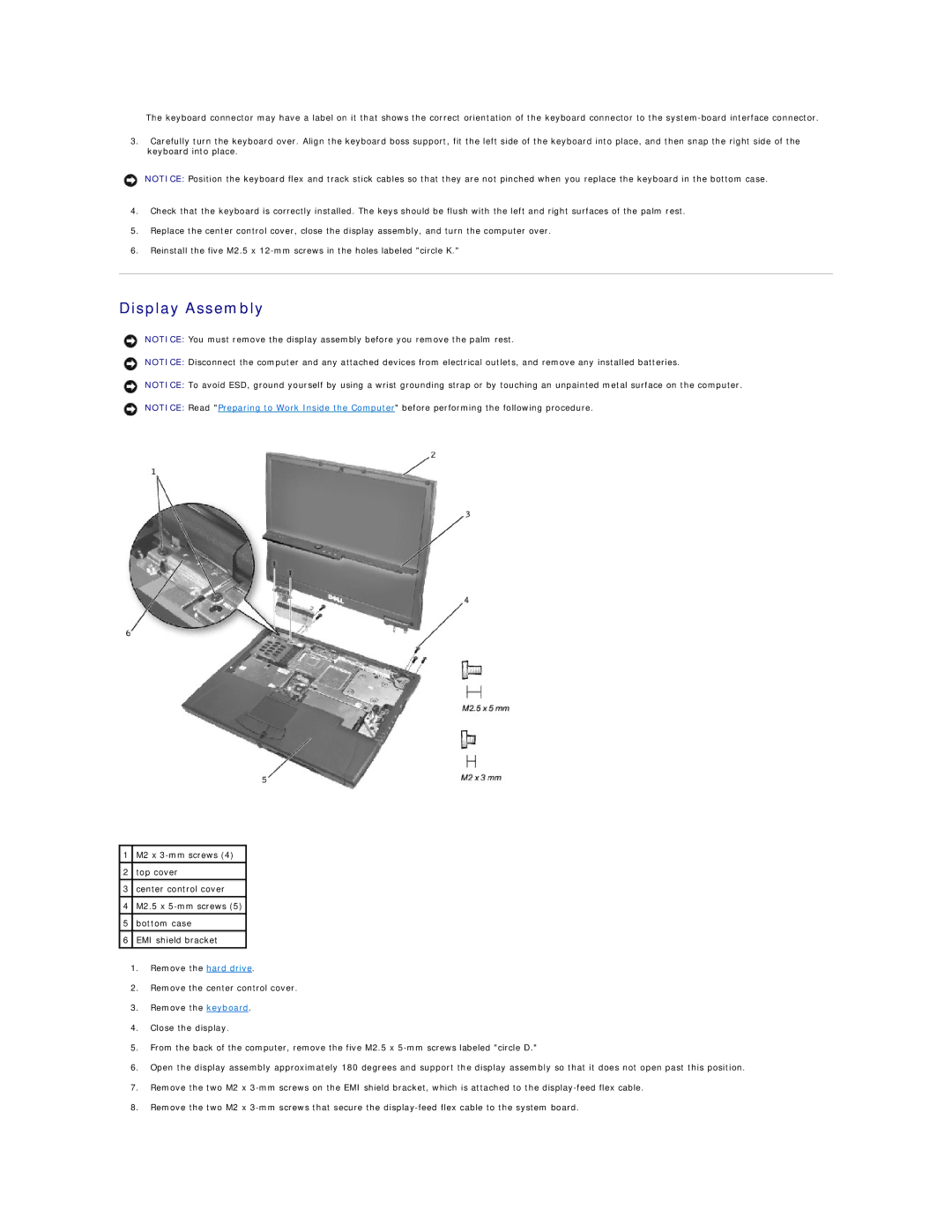
1 | M2 x |
|
|
2 | top cover |
|
|
3 | center control cover |
|
|
4 | M2.5 x |
|
|
5 | bottom case |
|
|
6 | EMI shield bracket |
|
|
1.Remove the hard drive.
2.Remove the center control cover.
3.Remove the keyboard.
4.Close the display.
5.From the back of the computer, remove the five M2.5 x
6.Open the display assembly approximately 180 degrees and support the display assembly so that it does not open past this position.
7.Remove the two M2 x
8.Remove the two M2 x
