Removing and Replacing Parts : Dell Latitude C600/C500 Series Service Manual
NOTE: Memory modules are keyed, or designed to fit into their sockets, in only one direction.
NOTICE: The memory module must be inserted at a
2.Align the memory module's edge connector with the slot in the center of the memory module socket. With the module at a
3.Pivot the memory module down until it clicks into place. If you do not hear a click, remove the memory module and reinstall it.
4.Insert the tabs on the memory module cover into the bottom case assembly. Rotate the memory module cover down and tighten the two captive screws.
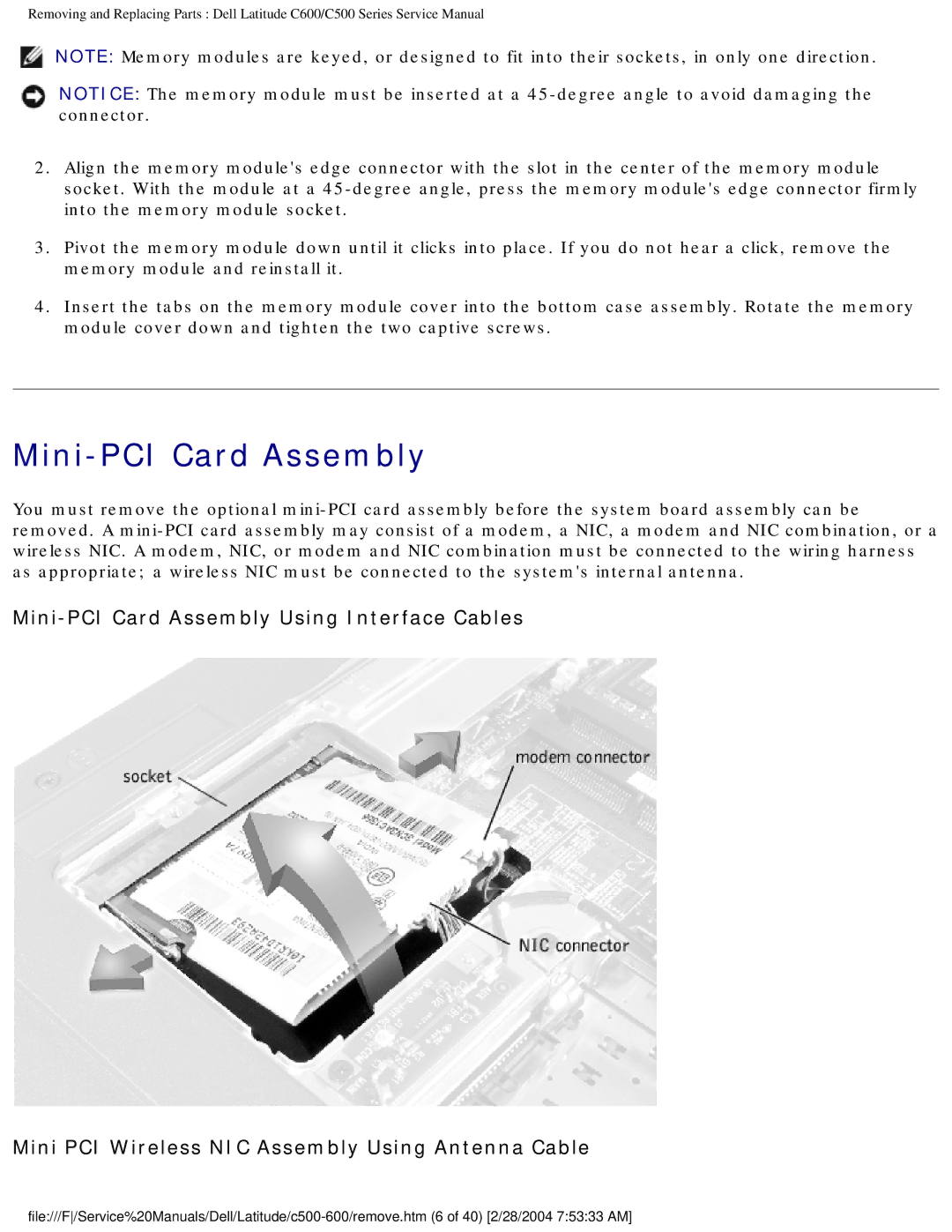
Mini-PCI Card Assembly
You must remove the optional
Mini PCI Wireless NIC Assembly Using Antenna Cable