Diagnostic lights
W . d e l l . c o m s u p p o r t . d e l l . c o m
January C7565
Contents
Solving Problems
Mail, Modem, and Internet Problems
Using Microsoft Windows XP System Restore
Addressing Memory With 4-GB Configurations
Resolving Software and Hardware Incompatibilities
Before Working Inside Your Computer
Connecting and Disconnecting Drive Cables
101
105
106
112
114
115
117
Contents
Finding Information
What Are You Looking For? Find it Here Warranty information
Finding Information
Use the Service Tag to
When you use
Warranty, and repair information
Specifications, and white papers
Setting Up a Printer
Connecting a USB Printer
Setting Up and Using Your Computer
Printer Cable
Connecting a Parallel Printer
USB connector on computer USB printer cable
Connecting to the Internet
Cable Notches
If you have a CD, click Use the CD I got from an ISP
Setting Up Your Internet Connection
Click Connect to the Internet
Playing CDs and DVDs
Adjusting the Volume
DVD player includes the following basic buttons
Adjusting the Picture
How to Copy a CD or DVD
Copying CDs and DVDs
Click Exact Copy
Using Blank CD-Rs and CD-RWs
Helpful Tips
Using a Media Card Reader Optional
Connecting Two Monitors
Connecting Two Monitors With VGA Connectors
Optional DVI adapter
Connecting a TV
TV-OUT connector VGA blue connector
Connecting to a Network Adapter
Setting Up a Home and Office Network
Changing the Display Settings
Power Management
Network Setup Wizard
Standby Mode
Click Checklist for creating a network
Power Schemes Tab
Hibernate Mode
Power Options Properties
Advanced Tab
Hibernate Tab
Hyper-Threading
Click Hardware and click Device Manager
Troubleshooting Tips
Battery Problems
Drive Problems
Solving Problems
CD and DVD drive problems
Problems writing to a CD/DVD-RW drive
Mail, Modem, and Internet Problems
Hard drive problems
Error Messages
Use these characters in filenames
Media Card Reader Problems
Keyboard Problems
Lockups and Software Problems
Computer does not start up
Computer stops responding
Program stops responding
Program crashes repeatedly
Program is designed for an earlier Windows operating system
Solid blue screen appears
Memory Problems
Other software problems
Mouse Problems
Network Problems
Power Problems
Printer Problems
Scanner Problems
Sound and Speaker Problems
No sound from speakers
If the screen is blank
Video and Monitor Problems
No sound from headphones
If the screen is difficult to read
Solving Problems
Diagnostic Lights
Light Pattern Problem Description Suggested Resolution
Troubleshooting Tools
Computer is in a normal off condition None
Reinstall an additional module. Continue
Reinstalled all modules without error
If the problem persists, contact Dell see
Restart the computer
Module/memory connector placement
Ensure that no special memory
Requirements exist see
See
Dell Diagnostics
Dell Diagnostics Main Menu
Ensure that the cables are properly
Drive, CD drive, and DVD drive see
Option Function
Tab Function
What Is a Driver?
Reinstalling Drivers
Drivers
Identifying Drivers
Resolving Software and Hardware Incompatibilities
Using Windows XP Device Driver Rollback
Manually Reinstalling Drivers
Using Microsoft Windows XP System Restore
Creating a Restore Point
Restoring Your Operating System
Restoring the Computer to an Earlier Operating State
Enabling System Restore
Using Dell PC Restore by Symantec
Undoing the Last System Restore
Troubleshooting Tools
Removing and Installing Parts
Before You Begin
Recommended Tools
Turning Off Your Computer
Before Working Inside Your Computer
Front View of the Computer
System
System shutdown
Back View of the Computer
Power connector Insert the power cable
Removing the Computer Cover
Power supply
Inside View of Your Computer
System Board Components
Memory
DDR2 Memory Overview
Addressing Memory With 4-GB Configurations
Installing Memory
Notch Memory module Cutouts Crossbar
Cards
Removing Memory
Installing a PCI Card
PCI Cards
Removing and Installing Parts
Fully seated card
Removing a PCI Card
Installing a PCI Express Card
PCI Express Cards
Card retention door Card retention mechanism Release tabs
PCI Express
X16 card X1 card Securing tab
Fully seated card
Card retention door Card retention mechanism Release tabs
Removing a PCI Express Card
Sliding plate lever Drive panel
Drive Panels
Removing the Drive Panel
Drive panel Drive panel insert drive panel tabs
Removing the Drive-Panel Insert
Replacing the Drive-Panel Insert
Replacing the Drive Panel
Drives
IDE Drive Addressing
CD/DVD drives
Hard drives
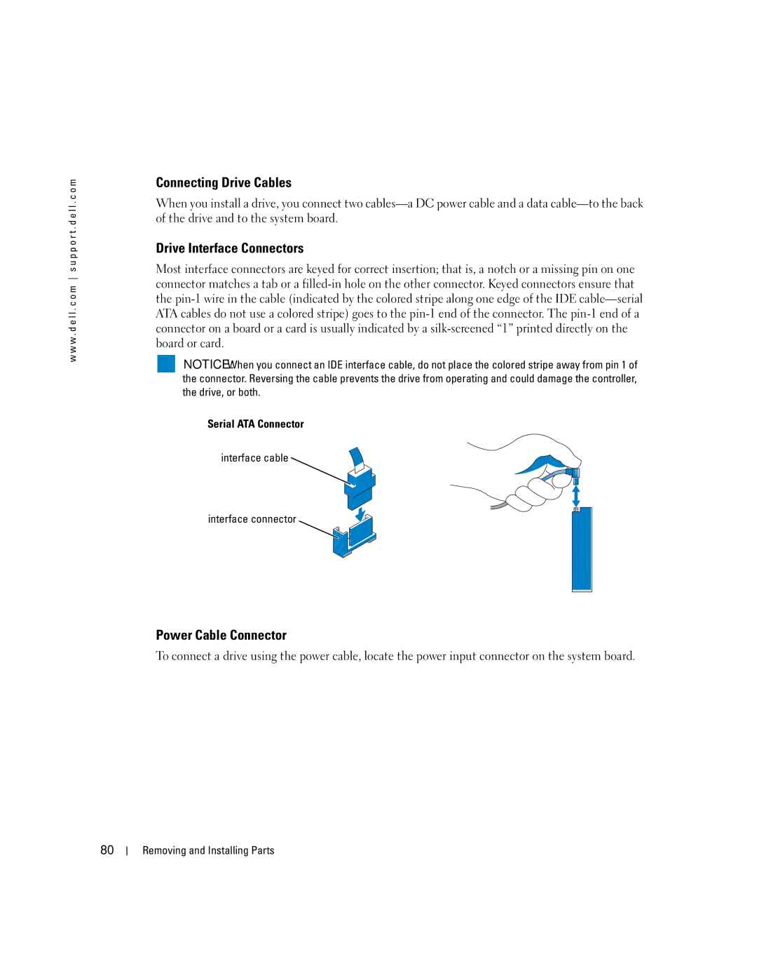
Connecting Drive Cables
Drive Interface Connectors
Power Cable Connector
Serial ATA Connector Interface cable Interface connector
Hard Drive
Connecting and Disconnecting Drive Cables
Power cable
Power cable Removing and Installing Parts
Removing a Hard Drive
Drive Bracket rails
Installing a Hard Drive
Tabs Hard drive
Adding a Second Hard Drive
Floppy Drive
Removing a Floppy Drive
Rail tabs
Hard drive bay
Data cable
Installing a Floppy Drive
Sliding plate lever Floppy drive
Drive Screws
Power cable Data cable
Media Card Reader
Removing a Media Card Reader
Cable Media Card Reader Not present on all computers
Sliding plate lever Media Card Reader
Installing a Media Card Reader
Media Card Reader Screws
CD/DVD Drive
FlexBay cable Media Card Reader
Data cable Power cable Removing and Installing Parts
Removing a CD/DVD Drive
Installing a CD/DVD Drive
Sliding plate lever CD/DVD drive
Drive Screws Removing and Installing Parts
Data cable Power cable
Battery
Replacing the Battery
Battery Battery socket
Replacing the Computer Cover
100
Specifications
101
Eight-way set associative, write-back Sram
System clock MHz data rate Appendix
102
Connectors for headphones/microphone
103
CD drive, CD-RW drive, DVD drive, DVD-RW drive, and DVD
CD-RW combo drive, and media reader
104
System Setup
Overview
105
50.8 cm/sec
106
Entering System Setup
System Setup Screens
107
System Setup Options
108
109
110
Boot Sequence
Option Settings
Changing Boot Sequence for the Current Boot
111
112
Clearing Forgotten Passwords
Changing Boot Sequence for Future Boots
113
Clearing Cmos Settings
Cleaning Your Computer
Computer, Keyboard, and Monitor
114
Mouse
Floppy Drive
CDs and DVDs
115
Definition of Dell-Installed Software and Peripherals
Dell Technical Support Policy U.S. Only
FCC Notices U.S. Only
Definition of Third-Party Software and Peripherals
Class a Class B
117
118
Contacting Dell
FCC Identification Information
119
120
121
122
123
124
125
126
127
128
129
Countries Sales Penang, Malaysia
Switchboard Sales
130
131
Trinidad/Tobago General Support Turks and Caicos Islands
PowerConnect, and PowerVault Transaction Sales
132
133
134
Index
Index 135
Problems
Connection, setting up
Finding Information
136 Index
Index 137
USB
138 Index
Wizard, 33 reinstalling, 50 scanner, 39 System Restore
Index 139
140 Index