2 | Common (black) | 12 | Common (black) |
3 | +5 VDC (red) | 13 | Common (black) |
4 | Common (black) | 14 | Common (black) |
5 | PWRGOOD1 (orange) | 15 | |
6 | +5 VFP (purple) | 16 | +5 VDC (red) |
7 | +12 VDC (yellow) | 17 | +5 VDC (red) |
8 | 18 | +5 VDC (red) | |
9 | Common (black) | 19 | Not connected |
10 | Common (black) | 20 | +5 VDC (red) |
1Pin 5 — PWRGOOD is a status signal generated by the power supply to notify the computer that the DC operating voltages are within the ranges required for proper computer operation.
2Pin 11 — PSON# is activated by pressing and releasing the power button while the power supply is in standby state. Activating PSON# connects the power supply's PSON# input to ground, thereby switching the power supply to
DC Power Connector P2
1Common (black)
2Common (black)
3Common (black)
4+3.3 VDC (orange)
5+3.3 VDC (orange)
6+3.3 VDC (orange)
DC Power Connector P3
1+12 VDC (yellow)
2Common (black)
3Common (black)
4+5 VDC (red)
DC Power Connectors P4, P5, and P6
1+12 VDC (yellow)
2Common (black)
3Common (black)
4+5 VDC (red)
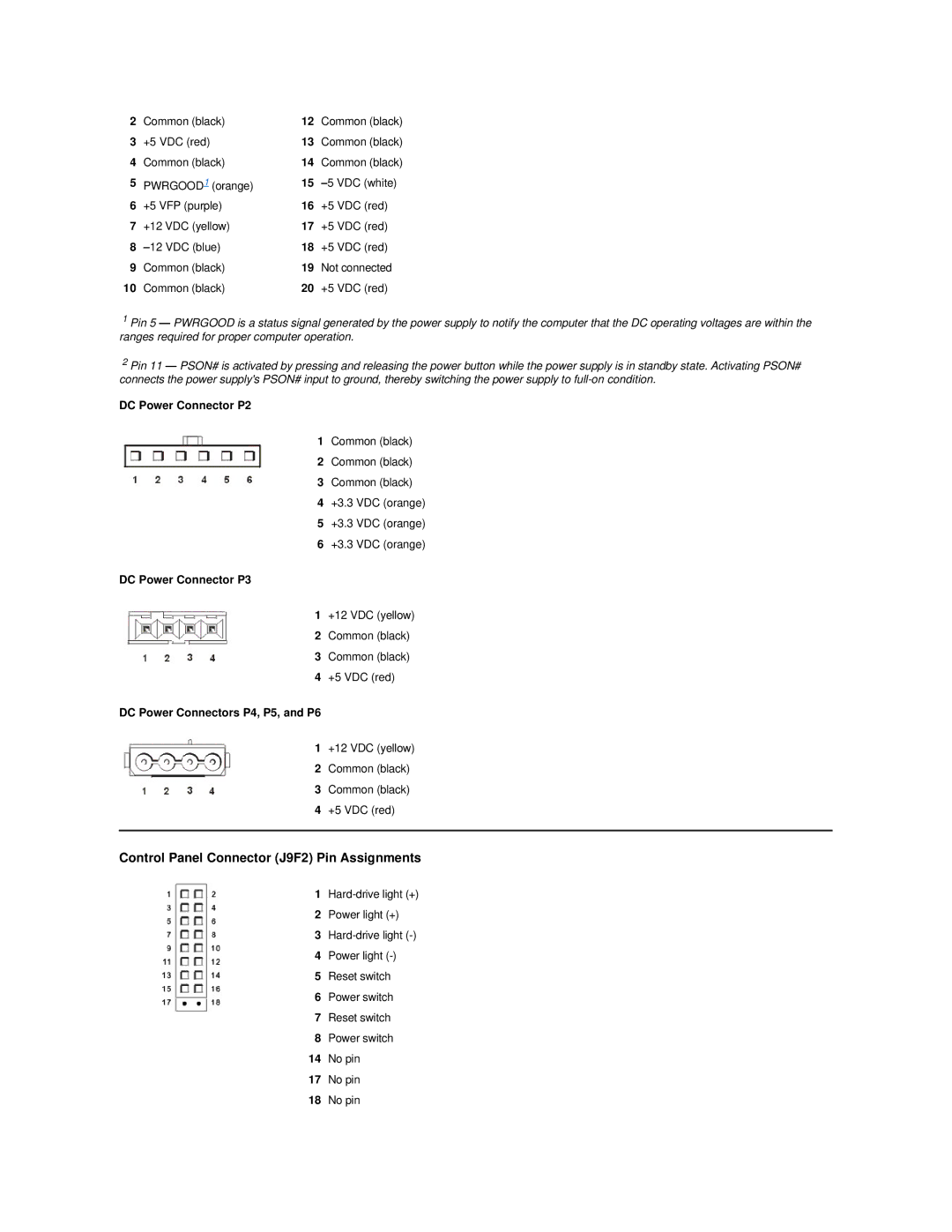
Control Panel Connector (J9F2) Pin Assignments
1
2Power light (+)
3
4Power light
5Reset switch
6Power switch
7Reset switch
8Power switch
14No pin
17No pin
18No pin