SMB Power (I2 C)
Connector
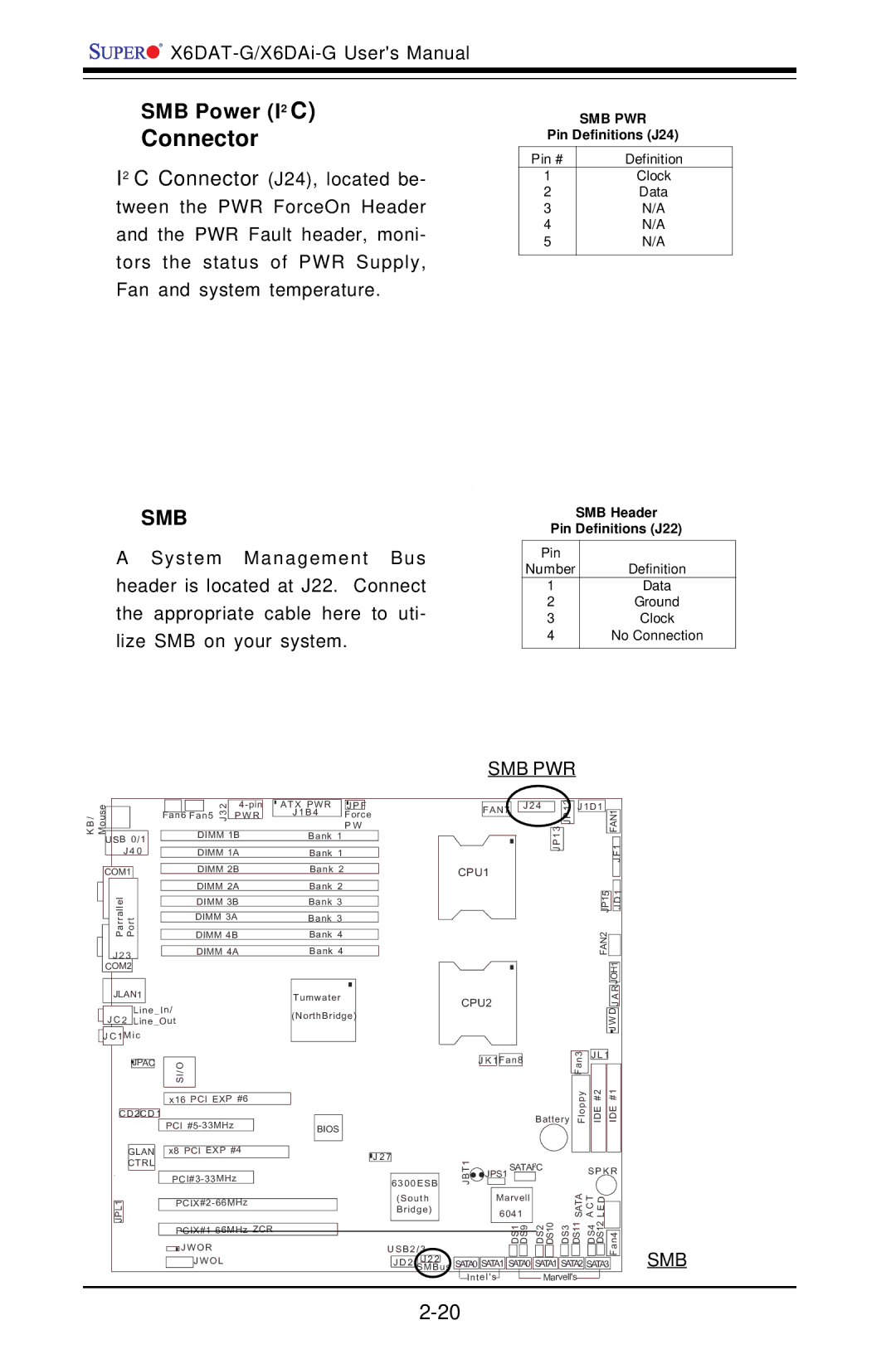
I2 C Connector (J24), located be- tween the PWR ForceOn Header and the PWR Fault header, moni- tors the status of PWR Supply, Fan and system temperature.
SMB
A System Management Bus header is located at J22. Connect the appropriate cable here to uti- lize SMB on your system.
SMB PWR
Pin Definitions (J24)
Pin # | Definition |
1 | Clock |
2 | Data |
3 | N/A |
4 | N/A |
5 | N/A |
|
|
SMB Header
Pin Definitions (J22)
Pin |
|
Number | Definition |
1 | Data |
2 | Ground |
3 | Clock |
4 | No Connection |
|
|
SMB PWR
/seu BK oM
USB 0/1
J 4 0
COM1
ParrallelJLAN1 Port
J 2 3
COM2
|
|
| 3 2 |
| ATX PWR | J P F |
| |
|
|
|
|
| J1B4 | Force | ||
Fan6 |
| P W R | ||||||
Fan5 J |
|
| ||||||
|
|
|
|
|
|
| P W | |
|
| DIMM 1B |
| Bank 1 |
|
| ||
|
|
|
|
|
|
|
|
|
|
| DIMM 1A |
| Bank 1 |
|
| ||
|
|
|
|
|
|
|
|
|
|
| DIMM 2B |
| Bank 2 |
|
| ||
|
|
|
|
|
|
|
|
|
|
| DIMM 2A |
| Bank 2 |
|
| ||
|
|
|
|
|
|
|
|
|
|
| DIMM 3B |
| Bank 3 |
|
| ||
|
|
|
|
|
|
|
|
|
|
| DIMM 3A |
| Bank 3 |
|
| ||
|
|
|
|
|
|
|
|
|
|
| DIMM 4B |
| Bank 4 |
|
| ||
|
|
|
|
|
|
|
|
|
|
| DIMM 4A |
| Bank 4 |
|
| ||
|
|
| J 2 4 |
| 2 | J1D1 |
|
|
|
| ||
| FAN7 |
|
|
| JP 1 |
|
|
|
| |||
|
|
|
| 3 |
|
|
|
|
| FAN1 |
| |
|
|
|
|
|
|
|
|
|
| |||
|
|
|
| JP 1 |
|
|
|
| F1 |
| ||
|
|
|
|
|
|
|
|
|
| |||
|
|
|
|
|
|
|
|
|
| J |
| |
CPU1 |
|
|
|
|
|
|
|
|
|
| ||
|
|
|
|
|
|
|
|
|
| 1 |
| |
|
|
|
|
|
|
|
| JP15 |
| D |
| |
|
|
|
|
|
|
|
|
| J |
| ||
|
|
|
|
|
|
| FAN2 |
|
|
|
| |
|
|
|
|
|
|
|
|
|
|
| ||
|
|
|
|
|
|
|
|
|
|
|
|
|
|
|
|
|
|
|
|
|
|
| JOH1 |
| |
|
|
|
|
|
|
|
|
|
| R |
|
|
JLAN1 |
| Tumwater | ||
|
| Line_In/ | (NorthBridge) | |
J C 2 | Line_Out | |||
|
|
| ||
J C 1 | Mic |
| ||
|
|
|
|
|
CPU2 | A |
J |
J W D |
| JPAC |
|
| I/OS |
|
|
|
|
|
|
|
|
|
| |
|
|
|
|
|
|
| |
|
|
|
| x16 PCI EXP #6 |
| ||
|
|
|
|
|
|
|
|
C D 2C D 1 |
|
|
|
|
| ||
|
|
|
|
|
|
| |
|
|
|
| PCI |
|
| |
|
|
|
|
|
| ||
| GLAN |
|
| x8 PCI EXP #4 |
| ||
| CTRL |
|
|
|
|
|
|
|
|
|
|
|
| ||
BIOS
![]()
![]()
![]() J 2 7
J 2 7
6300ESB
| J K 1Fan8 | Fan3 | J L 1 |
|
|
|
| ||
|
|
|
| |
| Battery | Floppy | IDE #2 | IDE #1 |
T1 | SATAI2C |
| S P K R | |
B | JPS1 |
|
|
|
J |
|
|
|
|
1 |
|
| ||
LJP |
|
|
|
|
|
|
| ||
|
|
| ||
|
|
| JW O R | |
|
|
|
| JW O L |
|
|
|
| |
|
|
|
|
|
|
|
|
| 6041 |
|
|
|
|
|
|
| SATA TCA DEL |
| ||||||||||||
| (South |
|
| Marvell |
|
|
|
|
|
|
|
|
|
|
|
|
|
|
| |||||||||||
| Bridge) |
|
|
|
|
|
|
|
|
|
|
|
|
|
|
|
|
|
|
|
|
|
|
|
| |||||
|
|
|
|
|
|
|
|
|
|
|
|
|
|
|
|
| DS2 DS10 | DS3 |
| DS11 DS4 | DS12 |
|
|
| ||||||
|
|
|
|
|
|
|
|
|
|
|
|
|
|
|
|
|
|
|
|
| ||||||||||
|
|
|
|
|
|
|
|
|
|
| DS1 DS9 |
| ||||||||||||||||||
|
|
|
|
|
|
|
|
|
|
|
|
|
|
|
| |||||||||||||||
USB2/3 |
|
|
| Fan4 | ||||||||||||||||||||||||||
|
|
|
|
|
|
|
|
|
| |||||||||||||||||||||
|
|
|
|
|
|
|
|
|
|
|
|
|
|
|
|
|
|
|
|
|
|
| ||||||||
| J D 2 | J 2 2 |
| SATA0 | SATA1 | SATA0 |
| SATA1 | SATA2 | SATA3 |
| |||||||||||||||||||
| SMBus |
|
| |||||||||||||||||||||||||||
|
|
| ||||||||||||||||||||||||||||
|
|
|
|
|
| Intel's |
|
|
|
|
|
|
|
|
| Marvell's |
|
|
|
|
|
|
| |||||||
SMB