2-5 Connecting Cables
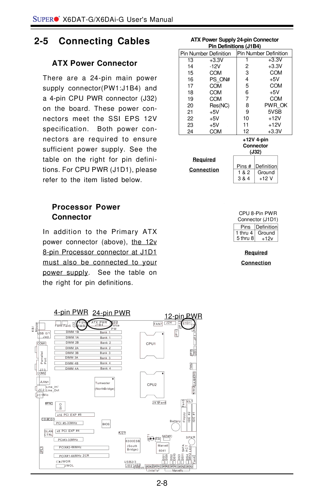
ATX Power Connector
There are a
a
ATX Power Supply 24-pin Connector
Pin Definitions (J1B4)
Pin Number Definition | Pin Number Definition | ||
13 | +3.3V | 1 | +3.3V |
14 | 2 | +3.3V | |
15 | COM | 3 | COM |
16 | PS_ON# | 4 | +5V |
17 | COM | 5 | COM |
18 | COM | 6 | +5V |
19 | COM | 7 | COM |
20 | Res(NC) | 8 | PWR_OK |
21 | +5V | 9 | 5VSB |
22 | +5V | 10 | +12V |
23 | +5V | 11 | +12V |
24 | COM | 12 | +3.3V |
| +12V | ||
| Connector | ||
| (J32) | ||
Required |
|
| |
Connection | Pins # | Definition | |
1 & 2 | Ground | ||
| |||
| 3 & 4 | +12 V | |
|
|
| |
Processor Power
Connector
In addition to the Primary ATX power connector (above), the 12v
CPU
Pins Definition
1 thru 4 | Ground |
5 thru 8 | +12v |
Required
Connection
/ouse
BK M
USB 0/1
J 4 0
COM1
ParrallelJLAN1 Port
J 2 3
COM2
| 2 |
| ATX PWR | J P F | |
Fan6 | 3 | P W R |
| J 1 B 4 | Force |
Fan5 J |
|
| |||
|
|
|
|
| P W |
| DIMM 1B |
| Bank 1 |
| |
|
|
|
|
|
|
| DIMM 1A |
| Bank 1 |
| |
|
|
|
|
|
|
| DIMM 2B |
| Bank 2 |
| |
|
|
|
|
|
|
| DIMM 2A |
| Bank 2 |
| |
|
|
|
|
|
|
| DIMM 3B |
| Bank 3 |
| |
|
|
|
|
|
|
| DIMM 3A |
| Bank 3 |
| |
|
|
|
|
|
|
| DIMM 4B |
| Bank 4 |
| |
|
|
|
|
|
|
| DIMM 4A |
| Bank 4 |
| |
FAN7
CPU1
J 2 4
J P 1 3 ![]()
![]() J P 1 2
J P 1 2
J1D1 |
|
|
| |
|
| FAN1 | ||
|
|
| JF1 | |
|
|
|
|
|
|
|
|
|
|
|
|
|
| 1 |
| 5 |
|
| |
| JP1 |
|
| D |
|
|
| J | |
FAN2 |
|
|
| |
|
|
| ||
|
|
|
|
|
|
|
| JOH1 | |
|
|
| R |
|
JLAN1 |
| Tumwater | ||
|
| Line_In/ | (NorthBridge) | |
J C 2 | Line_Out |
| ||
|
|
| ||
J C 1 | M ic |
| ||
|
|
|
|
|
CPU2
A |
J |
J W D |
|
|
| JPAC |
|
| I/OS |
|
|
| |||
|
|
|
|
|
|
|
|
|
| |||
|
|
|
|
|
|
|
|
|
|
|
|
|
|
|
|
|
|
|
|
|
|
|
|
| |
|
|
|
|
|
|
| x16 PCI EXP #6 | |||||
|
|
|
|
|
|
|
|
|
|
|
|
|
| C D 2 | C D 1 |
|
|
|
|
|
| ||||
|
|
|
|
|
|
| PCI |
|
| |||
|
|
|
|
|
|
|
|
|
|
| ||
|
|
| GLAN |
|
| x8 PCI EXP #4 |
| |||||
|
|
| CTRL |
|
|
|
|
|
|
|
| |
|
|
|
|
|
|
|
| |||||
|
|
|
|
|
|
| ||||||
| JPL1 |
|
|
|
|
| ||||||
|
|
| ||||||||||
|
|
|
|
|
|
| ||||||
|
|
|
|
|
|
| JWOR | |||||
|
|
|
|
|
|
|
|
| JWOL | |||
|
|
|
|
|
|
|
|
|
|
|
|
|
|
|
|
|
| 3 | J L 1 |
|
| ||
|
|
|
|
|
|
|
| J K 1 | Fan8 |
|
|
|
|
| Fan |
|
|
|
|
| |||
|
|
|
|
|
|
|
|
|
|
|
|
|
| Battery | Floppy | IDE #2 | IDE #1 |
| |||||
BIOS |
|
|
|
|
|
|
|
|
|
|
|
|
|
|
|
|
|
|
|
|
|
|
|
|
|
|
|
|
|
|
|
|
|
|
|
|
|
|
|
|
|
|
|
|
|
|
|
|
|
|
|
|
|
|
|
|
|
|
|
|
|
|
|
|
|
|
|
|
|
|
|
|
| J 2 7 |
|
|
|
| T1 |
|
|
|
|
|
|
|
|
|
|
|
|
|
|
|
|
|
|
|
|
|
|
|
|
|
| SATAI2C |
| S P K R | |||||||||||
|
|
| 6300E SB |
|
| B | JPS1 |
|
|
|
|
|
|
|
|
|
|
|
| ||||
|
|
|
|
|
|
| J |
|
|
|
|
|
|
|
|
|
| ATAS | CAT ELD |
|
| ||
|
|
|
|
|
|
|
|
| 6041 |
|
|
|
|
|
|
| |||||||
|
|
| (South |
|
|
|
| Marvell |
|
|
|
|
|
|
|
|
|
| |||||
|
|
| Bridge) |
|
|
|
|
|
|
|
|
| DS2 DS10 | DS3 |
| DS11 | DS4 | DS12 |
|
|
| ||
|
|
|
|
|
|
|
|
|
|
|
|
|
|
|
|
|
| ||||||
|
| U SB2/ 3 |
|
|
|
|
|
| DS1 DS9 |
| Fan4 |
| |||||||||||
|
|
|
|
|
|
|
|
|
|
|
| ||||||||||||
|
|
|
|
|
|
|
|
|
|
|
|
|
|
|
|
|
|
|
| ||||
|
|
| J D 2 | J 2 2 | us | SATA0 | SATA1 | SATA0 | SATA1 | SATA2 | SATA3 |
|
| ||||||||||
|
|
| SMB |
|
| ||||||||||||||||||
|
|
|
|
|
| ||||||||||||||||||
|
|
|
|
|
|
| Intel's |
|
|
|
| Marvell's |
|
|
|
|
|
| |||||