Chapter 2: Installation
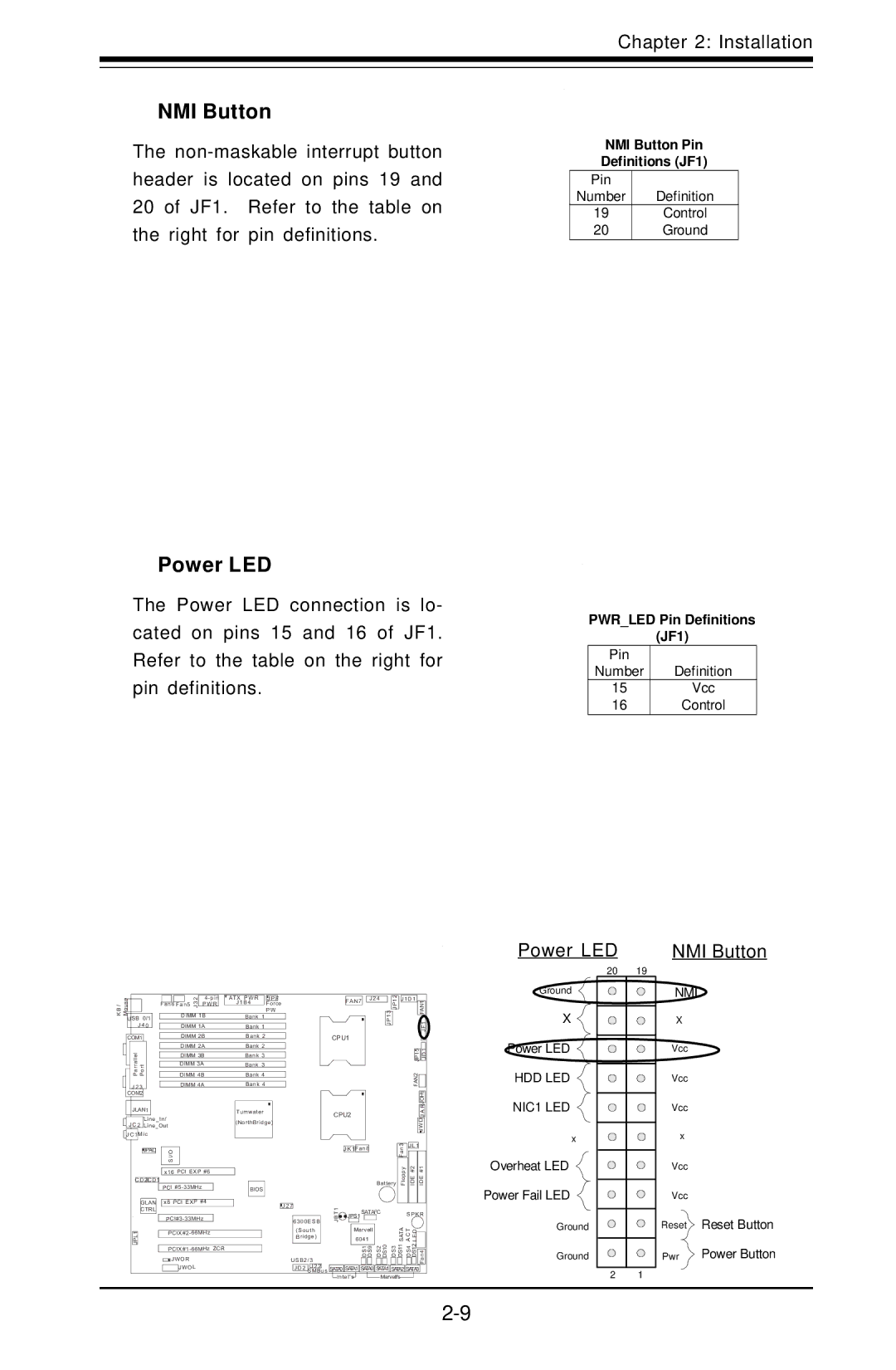
NMI Button
The
Power LED
The Power LED connection is lo- cated on pins 15 and 16 of JF1. Refer to the table on the right for pin definitions.
NMI Button Pin
Definitions (JF1)
Pin
Number Definition
19Control
20Ground
PWR_LED Pin Definitions
(JF1)
Pin |
|
Number | Definition |
15Vcc
16Control
Power LED | NMI Button |
20 | 19 |
| ouseMUSB 0/1 | 2 | ATX PWR | J P F |
| FAN7 | J 2 4 | 1 3 J P 12 | J1D1 | FAN1 | |||
| 3 | P W R | J 1 B 4 | Force |
|
|
|
|
| ||||
/B K | Fan6 Fan5 J |
|
|
|
|
|
|
| |||||
|
|
| P W |
|
|
|
|
|
| ||||
DIMM 1B | Bank 1 |
|
|
|
|
|
|
| |||||
| J 4 0 | DIMM 1A | Bank 1 |
|
|
|
|
| J P |
|
| F1 | |
|
|
|
|
|
|
|
|
|
|
|
|
| J |
| COM1 | DIMM 2B | Bank 2 |
| CPU1 |
|
|
|
|
|
| ||
|
| DIMM 2A | Bank 2 |
|
|
|
|
|
|
| 5 | 1 | |
|
|
|
|
|
|
|
|
|
|
|
| ||
| Parrallel Port | DIMM 3B | Bank 3 |
|
|
|
|
|
|
| JP1 | D | |
|
|
|
|
|
|
|
|
|
|
| J | ||
| DIMM 3A | Bank 3 |
|
|
|
|
|
|
|
|
| ||
| DIMM 4B | Bank 4 |
|
|
|
|
|
|
|
|
| ||
| J JLAN12 3 | DIMM 4A | Bank 4 |
|
|
|
|
|
|
| FAN2 | JOH1 | |
| COM2 |
|
|
|
|
|
|
|
|
|
|
| |
|
|
|
|
|
|
|
|
|
|
|
|
| |
| JLAN1 |
|
|
|
|
|
|
|
|
|
|
| R |
|
|
| Tumwater |
| CPU2 |
|
|
|
|
| A | ||
| Line_In/ |
|
|
|
|
|
|
|
| J | |||
|
| (NorthBridge) |
|
|
|
|
|
|
| D | |||
| J C 2 Line_Out |
|
|
|
|
|
|
|
| W | |||
|
|
|
|
|
|
|
|
|
|
|
|
| J |
| J C 1M ic |
|
|
|
|
|
|
|
|
|
|
|
|
|
|
|
|
|
|
|
|
|
|
| 3 | J L 1 |
|
| JPAC | I/O |
|
|
|
| J K 1Fan8 |
|
| Fan |
|
| |
|
|
|
|
|
|
|
|
|
|
|
| ||
|
| S |
|
|
|
|
|
|
|
|
|
|
|
|
| x16 PCI EXP #6 |
|
|
|
|
|
|
| Floppy | IDE #2 | IDE #1 | |
| C D 2C D 1 |
|
|
|
|
|
|
| Battery | ||||
|
| PCI |
|
|
|
|
|
| |||||
|
|
| BIOS |
|
|
|
|
|
|
|
|
| |
| GLAN | x8 PCI EXP #4 |
| J 2 7 |
|
|
|
|
|
|
|
| |
| CTRL |
|
|
| 1 |
|
|
|
|
|
|
| |
|
|
|
|
|
|
| 2 |
|
| S P K R | |||
|
|
|
|
|
| T | JPS1 | SATAI C |
|
| |||
|
|
| 6300E SB | B |
|
|
|
|
|
| |||
|
|
|
|
| J |
|
|
|
|
|
|
| |
| JPL1 |
| (South |
| Marvell |
|
| SATA ACT LED |
| ||||
|
|
|
| Bridge) |
| 6041 |
|
|
| ||||
|
|
|
|
| DS1 DS9 | DS2 | DS10 DS3 | DS11 | DS4 DS12 | Fan4 | |||
| JWOR |
|
| U SB2 / 3 |
|
| |||||||
|
| JWOL |
|
| J 2 2 |
| SATA1 SATA0 SATA1 SATA2 SATA3 |
| |||||
|
|
|
|
| J D 2 SMBus SATA0 |
| |||||||
|
|
|
|
|
| Intel's |
|
| Marvell's |
|
| ||
Ground
X ![]()
![]()
![]() Power LED
Power LED
HDD LED ![]()
![]()
![]() NIC1 LED
NIC1 LED
x
Overheat LED ![]()
Power Fail LED
Ground
Ground
2 1
NMI
X
Vcc
Vcc
Vcc
x
Vcc
Vcc
Reset Reset Button
Pwr ![]() Power Button
Power Button