Chapter 2: Installation
Power Fault
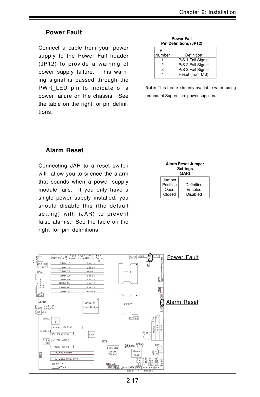
Connect a cable from your power supply to the Power Fail header (JP12) to provide a warning of power supply failure. This warn- ing signal is passed through the PWR_LED pin to indicate of a power failure on the chassis. See the table on the right for pin defini- tions.
Power Fail
Pin Definitions (JP12)
Pin |
|
Number | Definition |
1 | P/S 1 Fail Signal |
2 | P/S 2 Fail Signal |
3 | P/S 3 Fail Signal |
4 | Reset (from MB) |
|
|
Note: This feature is only available when using
redundant Supermicro power supplies.
Alarm Reset
Connecting JAR to a reset switch will allow you to silence the alarm that sounds when a power supply module fails. If you only have a single power supply installed, you should disable this (the default setting) with (JAR) to prevent false alarms. See the table on the right for pin definitions.
Alarm Reset Jumper
Settings
(JAR)
Jumper
Position Definition
Open Enabled
Closed Disabled
/Mouse
BK
USB 0/1
J 4 0
COM1
ParrallelJLAN1 Port
J 2 3
COM2
|
|
| 32 |
| ATX PWR | J P F |
| |
|
|
|
|
| J1B4 | Force | ||
Fan6 |
| P W R | ||||||
Fan5 J |
|
| ||||||
|
|
|
|
|
|
| P W | |
|
| DIMM 1B |
| Bank 1 |
|
| ||
|
|
|
|
|
|
|
|
|
|
| DIMM 1A |
| Bank 1 |
|
| ||
|
|
|
|
|
|
|
|
|
|
| DIMM 2B |
| Bank 2 |
|
| ||
|
|
|
|
|
|
|
|
|
|
| DIMM 2A |
| Bank 2 |
|
| ||
|
|
|
|
|
|
|
|
|
|
| DIMM 3B |
| Bank 3 |
|
| ||
|
|
|
|
|
|
|
|
|
|
| DIMM 3A |
| Bank 3 |
|
| ||
|
|
|
|
|
|
|
|
|
|
| DIMM 4B |
| Bank 4 |
|
| ||
|
|
|
|
|
|
|
|
|
|
| DIMM 4A |
| Bank 4 |
|
| ||
| FAN7 |
| J 2 4 |
| JP12 | J1D1 |
|
|
| |
|
|
|
|
|
|
| FAN1 | |||
|
|
|
|
|
|
|
| |||
|
|
|
|
|
|
|
|
| ||
|
|
|
| JP13 |
|
|
|
| F1 | |
|
|
|
|
|
|
|
|
| ||
|
|
|
|
|
|
|
|
| J | |
CPU1 |
|
|
|
|
|
|
|
| ||
|
|
|
|
|
|
|
|
|
|
|
|
|
|
|
|
|
|
|
|
| 1 |
|
|
|
|
|
|
| JP15 |
|
| D |
|
|
|
|
|
|
|
|
| J | |
|
|
|
|
|
| FAN2 |
|
|
| |
|
|
|
|
|
|
|
|
| ||
|
|
|
|
|
|
|
|
|
|
|
|
|
|
|
|
|
|
|
| JOH1 | |
|
|
|
|
|
|
|
|
| R |
|
Power Fault
JLAN1 |
| Tumwater | ||
|
| Line_In/ | (NorthBridge) | |
J C 2 | Line_Out | |||
|
|
| ||
J C 1 | Mic |
| ||
|
|
|
|
|
CPU2 | A |
J | |
| J WD |
Alarm Reset
|
|
| JPAC |
|
| I/OS |
|
|
| ||
|
|
|
|
|
|
|
|
| |||
|
|
|
|
|
|
|
|
|
|
| |
|
|
|
|
|
| x16 PCI EXP #6 | |||||
|
|
|
|
|
|
|
|
|
|
|
|
| C D 2C D 1 |
|
|
|
|
|
| ||||
|
|
|
|
|
| PCI |
|
| |||
|
|
|
|
|
|
|
|
|
| ||
|
|
| GLAN |
|
| x8 PCI EXP #4 |
| ||||
|
|
| CTRL |
|
|
|
|
|
|
|
|
|
|
|
|
|
|
| |||||
|
|
|
|
|
| ||||||
| JPL1 |
|
|
|
| ||||||
|
|
| |||||||||
|
|
|
|
|
| ||||||
|
|
|
|
|
| JW OR | |||||
|
|
|
|
|
|
|
| JW OL | |||
BIOS
|
|
|
|
|
|
|
|
|
|
|
|
|
|
|
| Fan3 | J L 1 |
|
| |||
|
|
|
|
|
| J K 1 | Fan8 |
|
|
|
|
|
|
|
|
|
|
|
|
|
| |
|
|
|
|
|
|
|
|
|
|
| Battery | Floppy | IDE #2 | IDE #1 |
| |||||||
|
|
|
|
|
|
|
|
|
|
|
|
|
|
|
|
|
|
|
|
|
|
|
J 2 7 |
|
| 1 |
|
| SATAI2C |
|
|
|
|
|
|
| |||||||||
|
|
|
|
|
|
| S P K R | |||||||||||||||
|
|
|
|
| BT |
| JPS1 |
|
| |||||||||||||
| 6300ESB |
|
|
|
|
|
|
|
|
|
|
|
|
|
|
|
|
|
| |||
|
|
|
|
| J |
|
|
|
|
|
|
|
|
|
| SATA | CAT ELD |
|
| |||
|
|
|
|
|
|
| 6041 |
|
|
|
|
|
|
|
|
| ||||||
| (South |
|
|
|
| Marvell |
|
|
|
|
|
|
|
|
|
|
|
|
| |||
| Bridge) |
|
|
|
|
|
|
|
|
|
|
|
|
|
|
|
|
|
|
|
| |
|
|
|
|
|
|
|
|
|
|
|
| DS2 DS10 | DS3 |
| DS11 | DS4 | DS12 |
|
|
| ||
|
|
|
|
|
|
| DS1 DS9 |
|
| |||||||||||||
|
|
|
|
|
|
|
|
|
|
|
| |||||||||||
USB2/3 |
|
|
|
|
|
|
|
|
|
|
|
|
|
|
|
|
|
| Fan4 |
| ||
| J D 2 | J 2 2 |
| SATA0 | SATA1 | SATA0 |
| SATA1 | SATA2 | SATA3 |
|
| ||||||||||
| SMBus |
|
|
| ||||||||||||||||||
|
|
|
| |||||||||||||||||||
|
|
|
|
| Intel's |
|
|
|
| Marvell's |
|
|
|
|
|
|
| |||||