F. Mechanical Cooling Lockout
Determine the
G. Dry Bulb Changeover Set Up
Determine the dry bulb changeover set point from Table 6. The settings are A, B, C and D. Locate the ECON SP potenti- ometer and set the dry bulb changeover set point. See Fig. 16. When the OAT is above this set point, the damper is limited to minimum position setting.
If a potentiometer fails, its setting will default to the values in Table 7.
Table 5 — EconoMi$er Switchover Control Strategy
ECONOMI$ER SWITCHOVER STRATEGY |
| SENSORS REQUIRED |
| ||
Outdoor Air Temperature | Outdoor Air Enthalpy | Return Air Temperature | Return Air Enthalpy | ||
| |||||
Dry Bulb | X |
|
|
| |
|
|
|
|
| |
Single Enthalpy |
| X |
|
| |
|
|
|
|
| |
Differential Temperature | X |
| X |
| |
|
|
|
|
| |
Differential Enthalpy* |
| X |
| X | |
|
|
|
|
| |
*Must be selected manually.
Table 6 — Changeover Set Points
SETTINGS | A | B | C | D | |
Dry Bulb (°F) | 73 | 69 | 66 | 63 | |
Single Enthalpy* (Btu/lb) | 27 | 25 | 24 | 22 | |
Differential Temperature* | 2 | 2 | 2 | 2 | |
(°F, Not Adjustable) | |||||
|
|
|
| ||
Differential Enthalpy* | 1 | 1 | 1 | 1 | |
(Btu/lb, Not Adjustable) | |||||
|
|
|
| ||
|
|
|
|
Table 7 — Default Potentiometer Settings
POTENTIOMETER | DEFAULT SETTING |
CO2 SP (PPM) | 1,000 |
MECH CLG LOCKOUT | 50 F |
ECON SP | D |
MIN POS (%) | 20 |
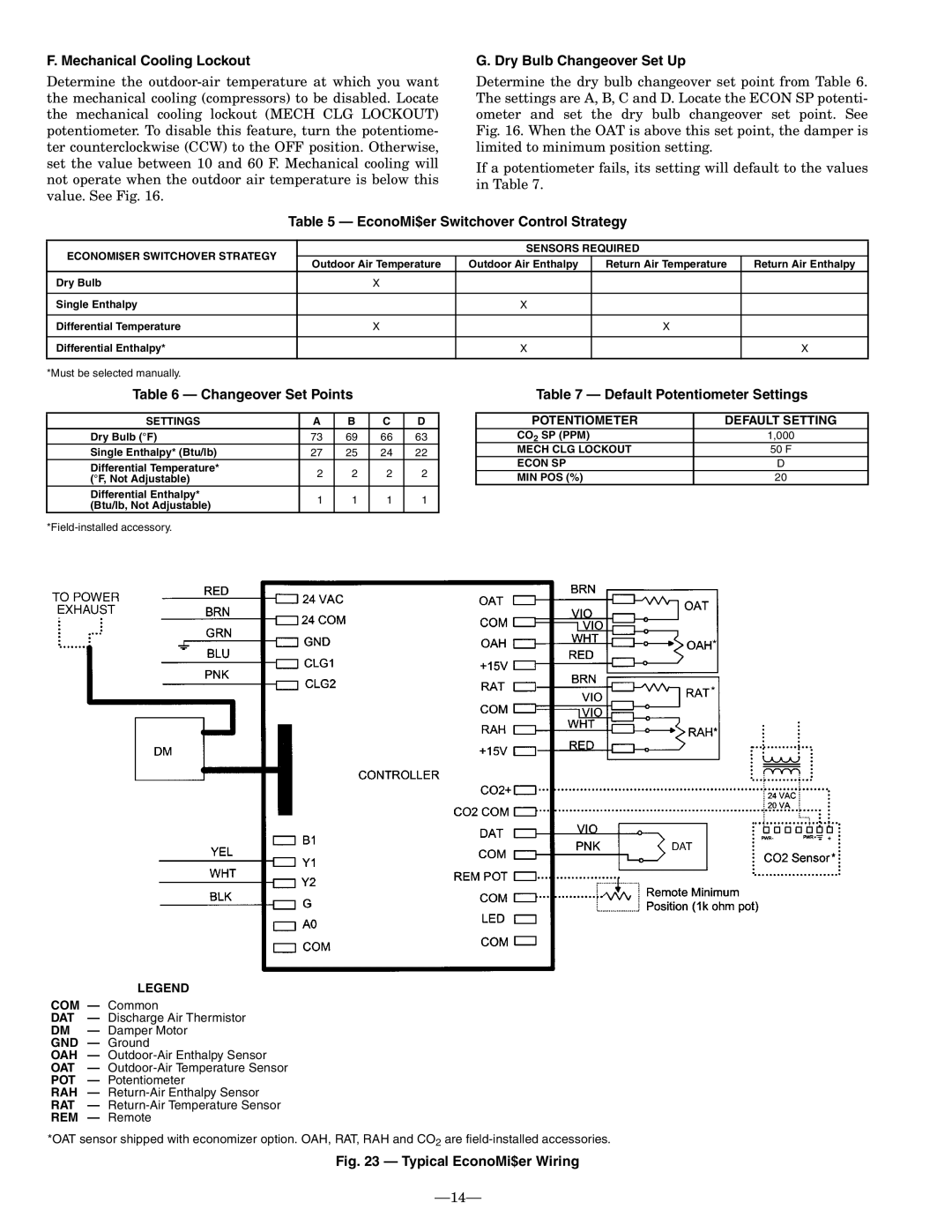
LEGEND
COM — Common
DAT — Discharge Air Thermistor
DM — Damper Motor
GND — Ground
OAH —
OAT —
POT — Potentiometer
RAH —
RAT —
REM — Remote
*OAT sensor shipped with economizer option. OAH, RAT, RAH and CO2 are
