LEGEND
FLA — Full Load Amps
HACR — Heating, Air Conditioning and Refrigeration
IFM — Indoor (Evaporator) Fan Motor
LRA — Locked Rotor Amps
MCA — Minimum Circuit Amps
MOCP— Maximum Overcurrent Protection
NEC — National Electrical Code
OFM — Outdoor (Condenser) Fan Motor
RLA — Rated Load Amps
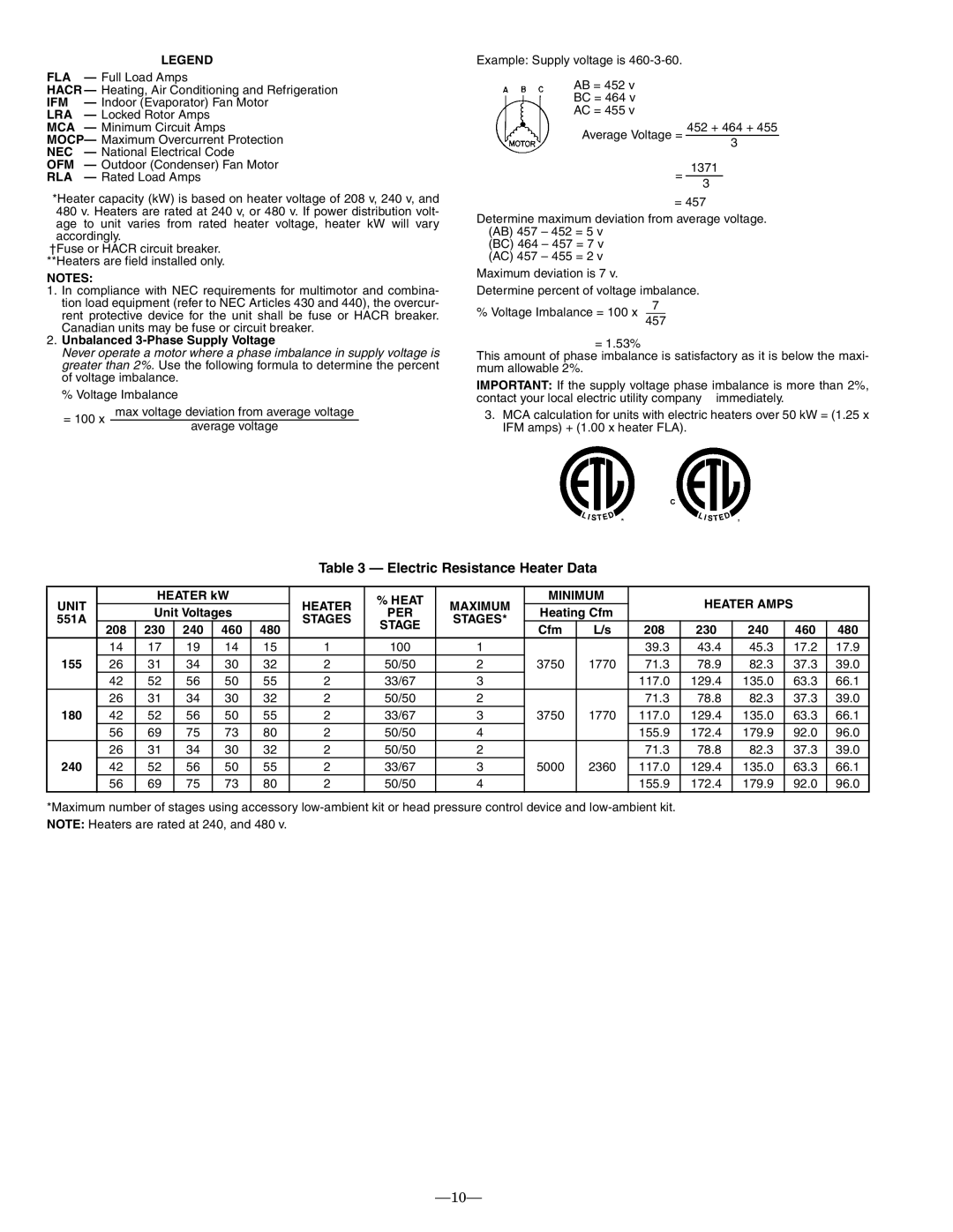
*Heater capacity (kW) is based on heater voltage of 208 v, 240 v, and 480 v. Heaters are rated at 240 v, or 480 v. If power distribution volt- age to unit varies from rated heater voltage, heater kW will vary accordingly.
†Fuse or HACR circuit breaker. **Heaters are field installed only.
NOTES:
1.In compliance with NEC requirements for multimotor and combina- tion load equipment (refer to NEC Articles 430 and 440), the overcur- rent protective device for the unit shall be fuse or HACR breaker. Canadian units may be fuse or circuit breaker.
2.Unbalanced 3-Phase Supply Voltage
Never operate a motor where a phase imbalance in supply voltage is greater than 2%. Use the following formula to determine the percent of voltage imbalance.
% Voltage Imbalance
= 100 x | max voltage deviation from average voltage | |
average voltage | ||
|
Example: Supply voltage is
AB = 452 v
BC = 464 v
AC = 455 v
452 + 464 + 455
Average Voltage =
3
1371
=
3
= 457
Determine maximum deviation from average voltage. (AB) 457 – 452 = 5 v
(BC) 464 – 457 = 7 v (AC) 457 – 455 = 2 v
Maximum deviation is 7 v.
Determine percent of voltage imbalance.
7
% Voltage Imbalance = 100 x 457
= 1.53%
This amount of phase imbalance is satisfactory as it is below the maxi- mum allowable 2%.
IMPORTANT: If the supply voltage phase imbalance is more than 2%, contact your local electric utility company immediately.
3.MCA calculation for units with electric heaters over 50 kW = (1.25 x IFM amps) + (1.00 x heater FLA).
Table 3 — Electric Resistance Heater Data
UNIT |
| HEATER kW |
| HEATER | % HEAT | MAXIMUM | MINIMUM |
| HEATER AMPS |
|
| |||||
| Unit Voltages |
| PER | Heating Cfm |
|
|
| |||||||||
551A |
|
| STAGES | STAGES* |
|
|
|
|
|
| ||||||
|
|
|
|
| STAGE |
|
|
|
|
|
|
|
| |||
| 208 | 230 | 240 | 460 | 480 |
|
| Cfm | L/s | 208 | 230 | 240 |
| 460 | 480 | |
|
|
|
|
| ||||||||||||
| 14 | 17 | 19 | 14 | 15 | 1 | 100 | 1 |
|
| 39.3 | 43.4 | 45.3 |
| 17.2 | 17.9 |
155 | 26 | 31 | 34 | 30 | 32 | 2 | 50/50 | 2 | 3750 | 1770 | 71.3 | 78.9 | 82.3 |
| 37.3 | 39.0 |
| 42 | 52 | 56 | 50 | 55 | 2 | 33/67 | 3 |
|
| 117.0 | 129.4 | 135.0 |
| 63.3 | 66.1 |
| 26 | 31 | 34 | 30 | 32 | 2 | 50/50 | 2 |
|
| 71.3 | 78.8 | 82.3 |
| 37.3 | 39.0 |
180 | 42 | 52 | 56 | 50 | 55 | 2 | 33/67 | 3 | 3750 | 1770 | 117.0 | 129.4 | 135.0 |
| 63.3 | 66.1 |
| 56 | 69 | 75 | 73 | 80 | 2 | 50/50 | 4 |
|
| 155.9 | 172.4 | 179.9 |
| 92.0 | 96.0 |
| 26 | 31 | 34 | 30 | 32 | 2 | 50/50 | 2 |
|
| 71.3 | 78.8 | 82.3 |
| 37.3 | 39.0 |
240 | 42 | 52 | 56 | 50 | 55 | 2 | 33/67 | 3 | 5000 | 2360 | 117.0 | 129.4 | 135.0 |
| 63.3 | 66.1 |
| 56 | 69 | 75 | 73 | 80 | 2 | 50/50 | 4 |
|
| 155.9 | 172.4 | 179.9 |
| 92.0 | 96.0 |
*Maximum number of stages using accessory
