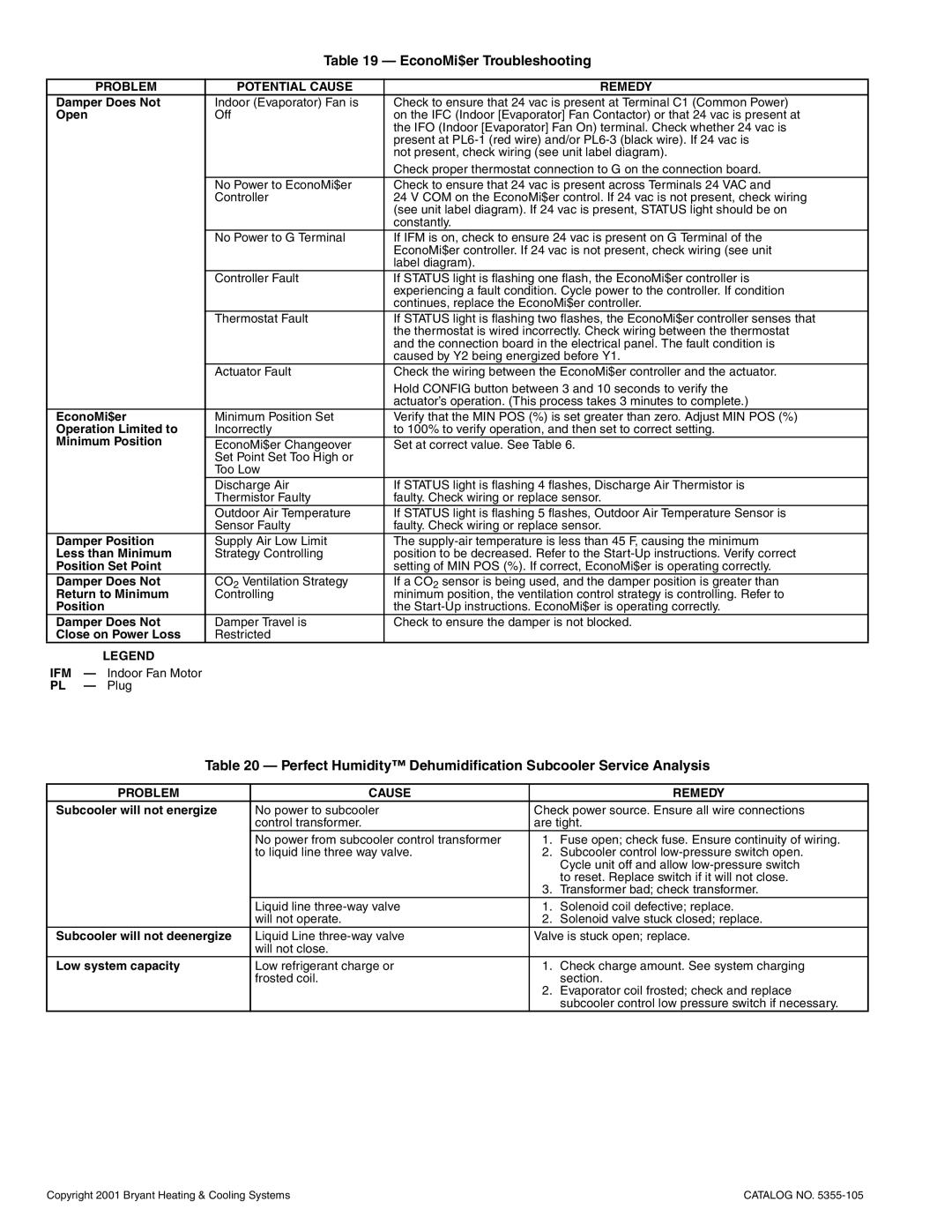
Table 19 — EconoMi$er Troubleshooting
| PROBLEM | POTENTIAL CAUSE | REMEDY |
Damper Does Not | Indoor (Evaporator) Fan is | Check to ensure that 24 vac is present at Terminal C1 (Common Power) | |
Open | Off | on the IFC (Indoor [Evaporator] Fan Contactor) or that 24 vac is present at | |
|
|
| the IFO (Indoor [Evaporator] Fan On) terminal. Check whether 24 vac is |
|
|
| present at |
|
|
| not present, check wiring (see unit label diagram). |
|
|
| Check proper thermostat connection to G on the connection board. |
|
| No Power to EconoMi$er | Check to ensure that 24 vac is present across Terminals 24 VAC and |
|
| Controller | 24 V COM on the EconoMi$er control. If 24 vac is not present, check wiring |
|
|
| (see unit label diagram). If 24 vac is present, STATUS light should be on |
|
|
| constantly. |
|
| No Power to G Terminal | If IFM is on, check to ensure 24 vac is present on G Terminal of the |
|
|
| EconoMi$er controller. If 24 vac is not present, check wiring (see unit |
|
|
| label diagram). |
|
| Controller Fault | If STATUS light is flashing one flash, the EconoMi$er controller is |
|
|
| experiencing a fault condition. Cycle power to the controller. If condition |
|
|
| continues, replace the EconoMi$er controller. |
|
| Thermostat Fault | If STATUS light is flashing two flashes, the EconoMi$er controller senses that |
|
|
| the thermostat is wired incorrectly. Check wiring between the thermostat |
|
|
| and the connection board in the electrical panel. The fault condition is |
|
|
| caused by Y2 being energized before Y1. |
|
| Actuator Fault | Check the wiring between the EconoMi$er controller and the actuator. |
|
|
| Hold CONFIG button between 3 and 10 seconds to verify the |
|
|
| actuator’s operation. (This process takes 3 minutes to complete.) |
EconoMi$er | Minimum Position Set | Verify that the MIN POS (%) is set greater than zero. Adjust MIN POS (%) | |
Operation Limited to | Incorrectly | to 100% to verify operation, and then set to correct setting. | |
Minimum Position | EconoMi$er Changeover | Set at correct value. See Table 6. | |
|
| Set Point Set Too High or |
|
|
| Too Low |
|
|
| Discharge Air | If STATUS light is flashing 4 flashes, Discharge Air Thermistor is |
|
| Thermistor Faulty | faulty. Check wiring or replace sensor. |
|
| Outdoor Air Temperature | If STATUS light is flashing 5 flashes, Outdoor Air Temperature Sensor is |
|
| Sensor Faulty | faulty. Check wiring or replace sensor. |
Damper Position | Supply Air Low Limit | The | |
Less than Minimum | Strategy Controlling | position to be decreased. Refer to the | |
Position Set Point |
| setting of MIN POS (%). If correct, EconoMi$er is operating correctly. | |
Damper Does Not | CO2 Ventilation Strategy | If a CO2 sensor is being used, and the damper position is greater than | |
Return to Minimum | Controlling | minimum position, the ventilation control strategy is controlling. Refer to | |
Position |
| the | |
Damper Does Not | Damper Travel is | Check to ensure the damper is not blocked. | |
Close on Power Loss | Restricted |
| |
| LEGEND |
|
|
IFM | — Indoor Fan Motor |
|
|
PL | — Plug |
|
|
Table 20 — Perfect Humidity™ Dehumidification Subcooler Service Analysis
PROBLEM | CAUSE |
| REMEDY |
Subcooler will not energize | No power to subcooler | Check power source. Ensure all wire connections | |
| control transformer. | are tight. | |
| No power from subcooler control transformer | 1. | Fuse open; check fuse. Ensure continuity of wiring. |
| to liquid line three way valve. | 2. | Subcooler control |
|
|
| Cycle unit off and allow |
|
|
| to reset. Replace switch if it will not close. |
|
| 3. | Transformer bad; check transformer. |
| Liquid line | 1. | Solenoid coil defective; replace. |
| will not operate. | 2. | Solenoid valve stuck closed; replace. |
Subcooler will not deenergize | Liquid Line | Valve is stuck open; replace. | |
| will not close. |
|
|
Low system capacity | Low refrigerant charge or | 1. | Check charge amount. See system charging |
| frosted coil. |
| section. |
|
| 2. | Evaporator coil frosted; check and replace |
|
|
| subcooler control low pressure switch if necessary. |
Copyright 2001 Bryant Heating & Cooling Systems | CATALOG NO. |
