H. Ventilation Air (Minimum Position Set Up)
If ventilation air is not required, skip this section. If ventila- tion air is required, perform the following:
1.The indoor fan must be on to set the ventilation air. Either put the thermostat in the continuous fan mode or jumper the R and G terminals at the rooftop unit connection board.
2.Locate the minimum position (MIN POS) potentiome- ter. Turn the potentiometer full CCW to fully close the outdoor air dampers. Turn the potentiometer gradually clockwise (CW) to the desired position. See Fig. 16.
3.Replace the filter access panel. See Fig. 18. Ensure the filter access panel is securely engaged.
4.Calculate the minimum airflow across the EconoMi$er.
a.Calculate % of outside air using the following formula.
% Outdoor air through EconoMi$er
% Outdoor | = | Mixture Temp – Return Air Temp | |
air | Outdoor Temp – Return Air Temp | ||
|
b.Multiply total CFM by percentage outdoor air, this gives outdoor air volume in CFM.
![]() WARNING: Personal Injury Hazard. Avoid possible injury by keeping fingers away from damper blades.
WARNING: Personal Injury Hazard. Avoid possible injury by keeping fingers away from damper blades.
IX. STEP 9 — INSTALL ALL ACCESSORIES
After all the
A. Motormaster® I Control Installation (551A155 and 180 Only)
Install
Wind baffles must be
![]() CAUTION: To avoid damage to the refrigerant coils and electrical components, use recommended screw sizes only. Use care when drilling holes.
CAUTION: To avoid damage to the refrigerant coils and electrical components, use recommended screw sizes only. Use care when drilling holes.
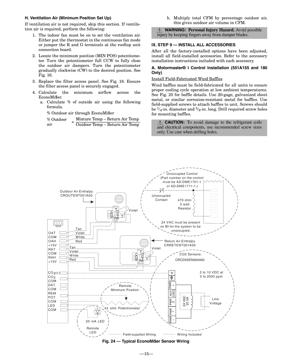
![]()
![]() Unoccupied Control (Part number on the control
Unoccupied Control (Part number on the control
must be
Outdoor Air Enthalpy |
|
|
|
CROUTENT001A00 |
| Unoccupied |
|
|
| Contact | 470 ohm |
|
|
| 5 watt |
| T | Violet | Resistor |
C |
| ||
O |
|
| |
O | U |
|
|
M | T T |
|
|
| PW |
|
|
|
| Tan |
OAT |
| Violet |
COM |
| W hite |
| ||
|
24 VAC must be present on BI for the system to be ![]()
![]() unoccupied.
unoccupied.
OAH |
| Red | |||||||||
| |||||||||||
+15V |
|
|
|
|
|
|
|
|
| Tan | |
|
|
|
|
|
|
|
|
| |||
RAT |
|
|
|
|
|
|
|
|
|
| |
|
|
|
|
|
|
|
|
|
| Violet | |
COM |
|
|
|
|
|
|
|
|
|
| |
RAH |
|
|
|
|
|
|
|
| W hite | ||
|
| Red | |||||||||
+15V |
|
|
|
|
|
| |||||
|
|
|
|
|
|
| |||||
CO 2(+) |
|
|
|
|
| ||||||
|
|
|
|
| |||||||
CO 2 |
|
|
|
|
| ||||||
COM |
|
|
|
|
| ||||||
DAT |
|
|
|
|
| ||||||
|
|
|
|
| |||||||
|
|
|
|
| |||||||
COM |
|
|
|
|
| ||||||
|
|
|
|
| |||||||
|
|
|
|
|
| ||||||
REM |
| ||||||||||
POT |
|
| |||||||||
|
| ||||||||||
COM |
|
| |||||||||
|
| ||||||||||
LED |
|
| |||||||||
|
|
| |||||||||
|
|
| |||||||||
COM |
|
| |||||||||
|
| ||||||||||
Violet
C TO
O U ![]()
![]()
M T T
PW
Remote
Minimum Position
1k ohm Potentiometer
20 mA LED
Remote
LED
Return Air Enthalpy
CRRETENT001A00
CO2 Sensors:
CRCDXSEN004A00
|
| 2 to 10 VDC at |
|
| 0 to 2000 ppm |
NOT 2 USED | VAC24 VA20 | Line |
|
| |
|
| Voltage |
1 |
|
|
- |
|
|
W iring Included