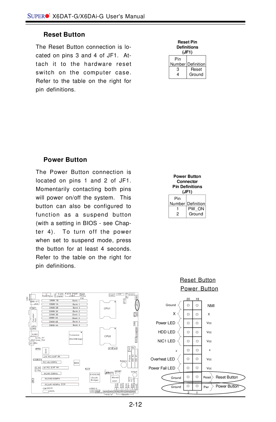
Reset Button
The Reset Button connection is lo- cated on pins 3 and 4 of JF1. At- tach it to the hardware reset switch on the computer case. Refer to the table on the right for pin definitions.
Power Button
The Power Button connection is located on pins 1 and 2 of JF1. Momentarily contacting both pins will power on/off the system. This button can also be configured to function as a suspend button (with a setting in BIOS - see Chap- ter 4). To turn off the power when set to suspend mode, press the button for at least 4 seconds. Refer to the table on the right for pin definitions.
Reset Pin
Definitions
(JF1)
Pin
Number Definition
3Reset
4Ground
Power Button
Connector
Pin Definitions
(JF1)
Pin
Number Definition
1PW_ON
2Ground
Reset Button
Power Button
es |
|
|
|
| 32 |
| ATX PWR | J P F | |
|
|
| Fan6 Fan5 | P W R |
| J 1 B 4 | Force | ||
/B uo K M |
|
|
| J |
|
| |||
|
|
|
|
|
|
| P W | ||
|
|
|
|
|
|
|
| ||
|
|
| DIMM 1B |
| Bank 1 |
| |||
USB 0/1 |
|
|
|
|
|
|
| ||
| J 4 0 |
|
|
|
|
|
|
| |
FAN7
J 2 4
JP1 3 ![]()
![]() JP1 2
JP1 2
J1D1 |
FAN1 |
1 |
20 19
|
|
|
|
|
|
|
| DIMM 1A | Bank 1 | |
|
|
|
|
|
|
|
| |||
|
|
|
|
|
|
|
|
|
| |
| COM1 |
|
|
|
| DIMM 2B | Bank 2 | |||
|
|
|
|
|
| |||||
|
|
|
|
|
|
|
| DIMM 2A | Bank 2 | |
| ParrallelJLAN1 Port |
|
|
|
|
|
|
|
| |
|
|
|
|
|
| DIMM 3B | Bank 3 | |||
|
|
|
|
|
|
|
|
| ||
|
|
|
|
|
| DIMM 3A | Bank 3 | |||
|
|
|
|
|
|
|
| |||
|
|
|
|
| DIMM 4B | Bank 4 | ||||
| J 2 3 |
|
|
| DIMM 4A | Bank 4 | ||||
|
|
|
|
| ||||||
| COM2 |
|
|
|
|
|
|
|
| |
| JLAN1 |
|
| Tumwater |
| |||||
|
|
| Line_In/ |
| (NorthBridge) |
| ||||
| J C 2 | Line_Out |
|
| ||||||
|
|
|
|
|
| |||||
| J C 1 | M ic |
|
|
| |||||
|
|
|
|
|
|
|
|
|
|
|
CPU1
CPU2
|
|
| JF | ||
|
|
|
|
|
|
|
|
| 1 |
| |
| 5 |
|
| ||
| JP1 |
| D |
| |
|
| J |
| ||
FAN2 |
|
|
|
| |
|
|
|
| ||
|
|
|
|
|
|
|
|
| JOH1 |
|
|
|
|
| R |
|
|
|
|
| A |
|
|
|
|
| J |
|
|
|
| J WD |
|
| |
Ground
X ![]()
![]()
![]() Power LED
Power LED
HDD LED 

 NIC1 LED
NMI
X
Vcc
Vcc
Vcc
|
| JPAC |
|
| I/OS |
|
|
| |
|
|
|
|
|
|
|
| ||
|
|
|
|
|
|
|
|
| |
|
|
|
|
| x16 PCI EXP #6 | ||||
|
|
|
|
|
|
|
|
|
|
C D 2C D 1 |
|
|
|
|
| ||||
|
|
|
|
| PCI |
|
| ||
|
|
|
|
|
|
| |||
|
| GLAN |
| x8 PCI EXP #4 |
| ||||
|
| CTRL |
|
|
|
|
|
| |
|
|
|
|
|
| ||||
|
|
|
|
| |||||
1 |
|
|
|
| |||||
LPJ |
|
| |||||||
|
|
|
|
| |||||
|
|
|
|
| JW O R | ||||
|
|
|
|
|
| JW O L | |||
|
|
|
|
|
|
|
|
|
|
|
|
|
|
|
| 3 | J L 1 |
|
| ||
|
|
|
|
|
|
| J K 1 | Fan8 |
|
|
|
|
|
| Fan |
|
|
|
| ||
|
|
|
|
|
|
|
|
|
|
| Battery | Floppy | IDE #2 | IDE #1 |
| ||||||
BIOS |
|
|
|
|
|
|
|
|
|
|
|
|
|
|
|
|
|
|
|
|
|
|
|
|
|
|
|
|
|
|
|
|
|
|
|
|
|
|
|
|
|
|
|
|
|
|
|
|
|
|
|
|
|
|
|
|
|
|
|
|
|
|
|
|
|
|
| J 2 7 | 1 |
|
|
|
|
|
|
|
|
|
|
|
|
|
|
| |||
|
|
|
|
|
|
|
|
| 2 |
|
|
|
|
|
|
|
|
|
| ||
|
|
|
|
|
| T |
| S | ATAI |
| C |
|
| S P K R | |||||||
|
|
|
|
|
| B | JPS1 |
|
|
|
|
|
|
|
|
|
|
|
|
| |
|
|
| 6300E SB |
| J |
|
|
|
|
|
|
|
|
| ATAS | CAT ELD |
|
| |||
|
|
|
|
|
|
|
| 6041 |
|
|
|
|
|
|
|
| |||||
|
|
| (South |
|
|
| Marvell |
|
|
|
|
|
|
|
|
|
|
| |||
|
|
| Bridge) |
|
|
|
|
|
|
| DS2 DS10 | DS3 |
| DS11 | DS4 | DS12 |
|
| |||
|
|
|
|
|
|
|
|
|
|
|
|
|
|
| |||||||
|
| U SB2/ 3 |
|
|
| DS1 DS9 |
|
|
| Fan4 |
| ||||||||||
|
|
|
|
|
|
|
|
|
|
|
|
|
|
|
|
|
| ||||
|
|
| J D 2 | J 2 2 | us | SATA0 | SATA1 | SATA0 | SATA1 | SATA2 | SATA3 |
|
| ||||||||
|
|
| SMB |
|
| ||||||||||||||||
|
|
|
|
|
| Intel's |
|
| Marvell's |
|
|
|
|
|
| ||||||
x
Overheat LED ![]()
Power Fail LED
Ground
Ground
2 1
x
Vcc
Vcc
Reset Reset Button
Pwr ![]() Power Button
Power Button