HDD LED
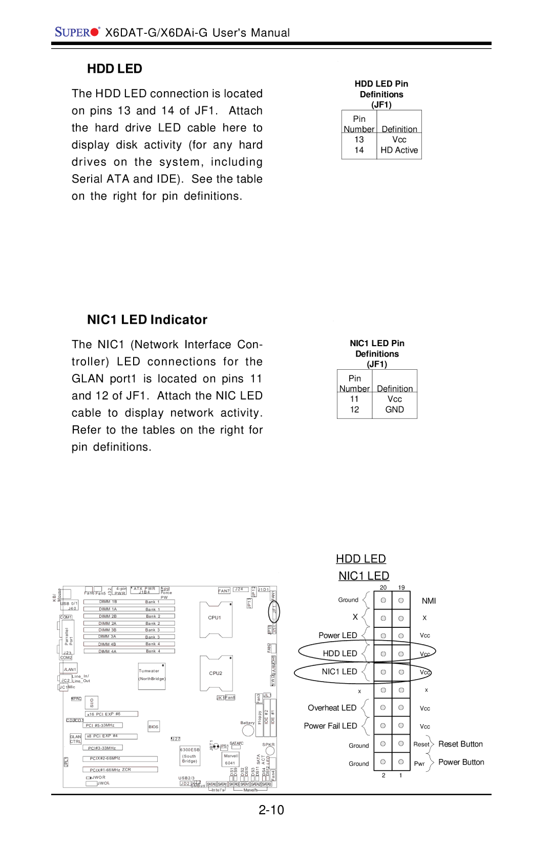
The HDD LED connection is located on pins 13 and 14 of JF1. Attach the hard drive LED cable here to display disk activity (for any hard drives on the system, including Serial ATA and IDE). See the table on the right for pin definitions.
HDD LED Pin
Definitions
(JF1)
Pin
Number Definition
13Vcc
14HD Active
NIC1 LED Indicator
The NIC1 (Network Interface Con- troller) LED connections for the GLAN port1 is located on pins 11 and 12 of JF1. Attach the NIC LED cable to display network activity. Refer to the tables on the right for pin definitions.
NIC1 LED Pin
Definitions
(JF1)
Pin
Number Definition
11Vcc
12GND
HDD LED
NIC1 LED
|
|
|
|
|
|
|
|
|
|
|
|
|
|
|
|
|
| es |
|
|
|
|
|
|
| Fan5 32 |
| ATX PWR | J P F | ||||
|
|
|
|
|
|
|
|
|
|
| J 1 B 4 |
|
| |||
|
|
|
|
|
|
| Fan6 | P W R |
|
| Force | |||||
/BK uoM |
|
|
|
|
|
|
|
|
| |||||||
|
|
|
|
|
|
| J |
|
|
|
| P W | ||||
|
|
|
|
|
|
|
|
|
|
|
| |||||
SB | 0/1 |
|
|
| DIMM 1B |
|
| Bank 1 |
|
| ||||||
|
|
|
|
|
|
|
|
|
|
|
|
| ||||
|
|
|
| J 4 0 |
|
|
| DIMM 1A |
|
| Bank 1 |
|
| |||
|
|
|
|
|
|
|
|
|
|
|
|
|
| |||
|
|
|
|
|
|
|
|
|
|
|
|
|
|
|
|
|
|
| COM1 |
|
|
|
| DIMM 2B |
|
| Bank 2 |
|
| ||||
|
|
|
|
|
|
|
|
|
| |||||||
|
|
|
|
|
|
|
|
|
| DIMM 2A |
|
| Bank 2 |
|
| |
|
|
| ParrallelJLAN1 | Port |
|
|
|
|
|
|
|
|
|
| ||
|
|
|
|
|
|
| DIMM 4B |
|
| Bank 4 |
|
| ||||
|
|
|
|
|
|
|
|
|
| DIMM 3B |
|
| Bank 3 |
|
| |
|
|
|
|
|
|
|
|
|
| DIMM 3A |
|
| Bank 3 |
|
| |
|
|
|
|
|
|
|
|
|
|
|
|
|
|
|
|
|
|
|
| J 2 3 |
|
|
|
| DIMM 4A |
|
| Bank 4 |
|
| |||
|
| COM2 |
|
|
|
|
|
|
|
|
|
|
|
|
| |
|
|
| JLAN1 |
|
|
|
|
| Tumwater |
|
| |||||
|
|
|
|
| Line_In/ |
|
|
|
| (NorthBridge) |
| |||||
|
|
| J C 2 |
| Line_Out |
|
|
|
|
| ||||||
|
|
|
|
|
|
|
|
|
|
|
| |||||
|
| J C 1 | M ic |
|
|
|
|
|
|
| ||||||
|
|
|
|
|
|
|
|
|
|
|
|
|
|
|
|
|
FAN7
CPU1
CPU2
J 2 4
JP1 3 ![]()
![]() JP1 2
JP1 2
J1D1 |
|
|
|
| |
|
| FAN1 | |||
|
|
| JF1 |
| |
|
|
|
|
|
|
|
|
| 1 |
| |
| 5 |
|
| ||
| JP1 |
| D |
| |
|
|
| J |
| |
FAN2 |
|
|
|
| |
|
|
|
| ||
|
|
|
|
|
|
|
|
| JOH1 |
|
|
|
|
| R |
|
|
|
|
| A |
|
|
|
|
| J |
|
|
|
| J WD |
|
| |
20 19
Ground
X ![]()
![]()
![]() Power LED
Power LED
HDD LED 

 NIC1 LED
x
NMI
X
Vcc
Vcc
Vcc
x
|
| JPAC |
|
| I/OS |
|
|
| |
|
|
|
|
|
|
|
| ||
|
|
|
|
|
|
|
|
| |
|
|
|
|
| x16 PCI EXP #6 | ||||
|
|
|
|
|
|
|
|
|
|
C D 2C D 1 |
|
|
|
|
| ||||
|
|
|
|
| PCI |
|
| ||
|
|
|
|
|
|
| |||
|
| GLAN |
| x8 PCI EXP #4 |
| ||||
|
| CTRL |
|
|
|
|
|
| |
|
|
|
|
|
| ||||
|
|
|
|
| |||||
1 |
|
|
|
| |||||
LPJ |
|
| |||||||
|
|
|
|
| |||||
|
|
|
|
| JW O R | ||||
|
|
|
|
|
| JW O L | |||
|
|
|
|
|
|
|
|
|
|
|
|
|
|
|
| 3 | J L 1 |
|
| ||
|
|
|
|
|
|
| J K 1 | Fan8 |
|
|
|
|
|
| Fan |
|
|
|
| ||
|
|
|
|
|
|
|
|
|
|
| Battery | Floppy | IDE #2 | IDE #1 |
| ||||||
BIOS |
|
|
|
|
|
|
|
|
|
|
|
|
|
|
|
|
|
|
|
|
|
|
|
|
|
|
|
|
|
|
|
|
|
|
|
|
|
|
|
|
|
|
|
|
|
|
|
|
|
|
|
|
|
|
|
|
|
|
|
|
|
|
|
|
|
|
| J 2 7 | 1 |
|
|
|
|
|
|
|
|
|
|
|
|
|
|
| |||
|
|
|
|
|
|
|
|
| 2 |
|
|
|
|
|
|
|
|
|
| ||
|
|
|
|
|
| T |
| S | ATAI |
| C |
|
| S P K R | |||||||
|
|
|
|
|
| B | JPS1 |
|
|
|
|
|
|
|
|
|
|
|
|
| |
|
|
| 6300E SB |
| J |
|
|
|
|
|
|
|
|
| ATAS | CAT ELD |
|
| |||
|
|
|
|
|
|
|
| 6041 |
|
|
|
|
|
|
|
| |||||
|
|
| (South |
|
|
| Marvell |
|
|
|
|
|
|
|
|
|
|
| |||
|
|
| Bridge) |
|
|
|
|
|
|
| DS2 DS10 | DS3 |
| DS11 | DS4 | DS12 |
|
| |||
|
|
|
|
|
|
|
|
|
|
|
|
|
|
| |||||||
|
| U SB2/ 3 |
|
|
| DS1 DS9 |
|
|
| Fan4 |
| ||||||||||
|
|
|
|
|
|
|
|
|
|
|
|
|
|
|
|
|
| ||||
|
|
| J D 2 | J 2 2 | us | SATA0 | SATA1 | SATA0 | SATA1 | SATA2 | SATA3 |
|
| ||||||||
|
|
| SMB |
|
| ||||||||||||||||
|
|
|
|
|
| Intel's |
|
| Marvell's |
|
|
|
|
|
| ||||||
Overheat LED ![]()
Power Fail LED
Ground
Ground
2 1
Vcc
Vcc
Reset Reset Button
Pwr ![]() Power Button
Power Button