Regulatory Model E19S Series Regulatory Type E19S001
Dell Inc. All Rights Reserved
Contents
Installing Memory Modules
Installing System Components
Memory Optimized Independent Channel Mode
Installing a Dual Slot Hard-Drive Blank
Installing The Power Supply Blank
Installing The Optical Drive
Expansion-Card Installation Guidelines
Internal USB Memory Key Optional
101
When To Use The Embedded System Diagnostics
111
123
113
117
141
Page
Front-Panel Features And Indicators
Indicator, Button, or Icon Description Connector
Use this button only if directed to do so by qualified
Front and the system status indicator on the back
USB connectors
Support personnel or by the operating systems
Home Screen
LCD Panel Features
Button Description
Setup Menu
View Menu
Off
Hard-Drive Indicator Patterns
Drive-Status Condition Indicator Pattern RAID Only
Seconds
Connects a PCI Express expansion card
Back-Panel Features And Indicators
Connector Through the optional cable management arm
Compliant
NIC Indicator Codes
Power Indicator Codes
Power supply and that the power supply is operational
AC power supply status indicator/handle
DC power supply status indicator
Flashing amber Indicates a problem with the power supply
Power Indicator Codes For Non-Redundant Power Supply
Diagnostic Indicator Condition Pattern Green
Other Information You May Need
F10
Choosing The System Boot Mode
Keystroke Description
F11 F12
Responding To Error Messages
Entering System Setup
Using The System Setup Navigation Keys
System Bios Screen
System Setup Options
System Setup Main Screen
System Information Screen
Memory Settings Screen
Processor Settings Screen
Execute Disable
Option is set to Enabled
Prefetcher option is set to Enabled
Execute Disable option is set to Enabled
Boot Settings Screen
Sata Settings Screen
Integrated Devices Screen
Serial Communications Screen
System Profile Settings Screen
System Security Screen
System And Setup Password Features
Miscellaneous Settings
Assigning a System And/Or Setup Password
Operating With a Setup Password Enabled
Entering The Uefi Boot Manager
Using Your System Password To Secure Your System
Boot Manager enables you to
Using The Boot Manager Navigation Keys
Boot Manager Screen
Entering The iDRAC Settings Utility
IDRAC Settings Utility
Uefi Boot Menu
Changing The Thermal Settings
Page
Page
Front Bezel Optional
Installing The Front Bezel
Recommended Tools
Release latch
Opening The System
Opening And Closing The System
Removing The Front Bezel
Keylock Front bezel Locking hook
Closing The System
Inside The System
System cover Latch Latch release lock
Heat sink for processor
Cooling shroud Cooling fans Expansion-card latch
DIMMs
Inside the System-Non-Redundant Power Supply Unit Chassis
Cooling Shroud
Removing and Installing the Cooling Shroud
Removing The Cooling Shroud
1333, 1066, Dual rank
Installing The Cooling Shroud
System Memory
1333, 1066 Dual rank Quad rank
Memory channels are organized as follows
Processor
Mode-Specific Guidelines
General Memory Module Guidelines
Advanced ECC Lockstep
Memory Sparing
Memory Optimized Independent Channel Mode
Sample Memory Configurations
Memory Mirroring
2R x4, 1600 MT/s B4, B5 192 2R x4, 1333 MT/s
2R x4, 1600 MT/s 2R x4, 1333 MT/s
2R x4, 1600 MT/s B3, B4, B5, B6
256 4R x4, 1066 MT/s
Removing Memory Modules
384 4R x4, 1066 MT/s
Installing Memory Modules
Removing The Memory Module
Installing The Memory Module
Hard Drives
Removing a 3.5 Inch Hard-Drive Blank
Installing a 3.5 Inch Hard-Drive Blank
Hard-drive blank Release button
Hard-Drive Blank Installation Sequence
Removing a Dual Slot Hard-Drive Blank
Removing a Hot-Swap Hard Drive
Installing a Dual Slot Hard-Drive Blank
Dual slot hard-drive blank Release tabs
Installing a Hot-Swap Hard Drive
Release button Hard drive Hard-drive carrier handle
Screws Inch hard-drive adapter Inch hard drive
Hard-drive carrier Screws Hard drive Screw holes
Hard-drive carrier Screws Hard-drive adapter Inch hard drive
Optical Drive Optional
Optical drive Power and data cable Release tab
Removing The Optical Drive
Cooling Fans
Installing The Optical Drive
Removing a Cooling Fan
Installing a Cooling Fan
Removing and Installing a Cooling Fan
Internal USB Memory Key Optional
Replacing the Internal USB Key
Expansion Card Slots
Expansion-Card Installation Guidelines
Expansion Cards And Expansion-Card Risers
Riser
External RAID CNAs Gb NICs
Removing An Expansion Card
Card Priority Card Type
Gb NICs Non-RAID
Expansion card Expansion-card latch Riser
Installing An Expansion Card
Riser Expansion-card latch Expansion card
Expansion-card riser Release tabs Riser guide pins Connector
Removing Expansion-Card Risers
Expansion-card riser Connector Riser guide pins
Installing Expansion-Card Risers
IDRAC Ports Card Optional
Removing The iDRAC Ports Card
Installing The iDRAC Ports Card
Removing and Installing the iDRAC Ports Card
Internal Dual SD Module
SD vFlash Card
Replacing An SD vFlash Card
Removing The Internal Dual SD Module
Blue pull tab Dual SD module SD card
Internal SD Card
Installing The Internal Dual SD Module
Installing An Internal SD Card
Removing An Internal SD Card
Integrated Storage Controller Card
Removing The Integrated Storage Controller
Storage connector on the system board
Installing The Integrated Storage Controller
Touch-points Release levers Storage-controller card
Processors
Removing a Processor
Removing and Installing the Heat Sink
Processor ZIF socket Processor shield
Installing a Processor
Notches in processor Socket keys
Power Supplies
Removing An AC Power Supply
Connector Power supply Release latch Power supply handle
Wiring Instructions For a DC Power Supply
Installing An AC Power Supply
Supply voltage -48-60 V DC Current consumption 32 a maximum
Safety ground wire
Grounding post #6-32 nut Locking washer
DC power socket Wire -48 Rubber cap Wire RTN Captive screws
DC power connector
Connector Release latch Power supply
Removing a DC Power Supply
Installing a DC Power Supply
Power supply status indicator
Installing The Power Supply Blank
Removing The Power Supply Blank
Power supply blank
Removing The Power-Distribution And Power-Interposer Boards
Power-distribution board
Power-interposer board Release tab
Power-Distribution Board Connectors
Power-Interposer Board Connectors
Removing a Non-Redundant Power Supply
Removing and Installing a Non-Redundant Power Supply
Standoff on the chassis
Installing a Non-Redundant Power Supply
Removing The Redundant Power Supply Unit Divider
Installing The Redundant Power Supply Unit Divider
Redundant power supply unit divider
Replacing The System Battery
System Battery
System battery Battery connector Locate the battery socket
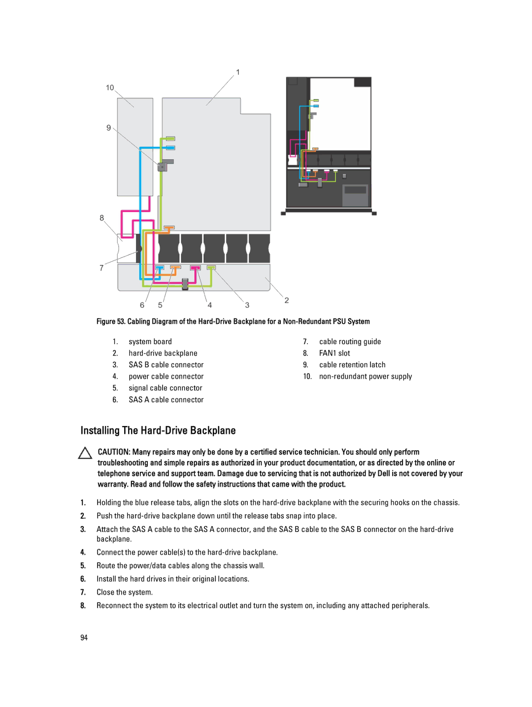
Hard-Drive Backplane
Removing The Hard-Drive Backplane
Backplane signal connector
Securing hooks
System board
Installing The Hard-Drive Backplane
Signal cable connector SAS a cable connector
Removing The Control-Panel Board
Control Panel Assembly
Control-panel board Screws Control-panel data cable
Removing The Control Panel
Installing The Control-Panel Board
USB cable
System Board
Installing The Control Panel
Notches on chassis front wall Control panel
Removing The System Board
Unpack the new system board assembly
Installing The System Board
Release screws System board holder
Page
Troubleshooting The Video Subsystem
Troubleshooting External Connections
Troubleshooting a USB Device
Troubleshooting a Serial I/O Device
Troubleshooting a NIC
Troubleshooting a Wet System
Troubleshooting a Damaged System
Troubleshooting The System Battery
Troubleshooting Power Supplies
Troubleshooting Cooling Fans
Troubleshooting Cooling Problems
Troubleshooting System Memory
Reseat the memory modules in their sockets Close the system
Troubleshooting An Internal USB Key
Troubleshooting An SD Card
106
Troubleshooting An Optical Drive
Troubleshooting a Hard Drive
Troubleshooting a Storage Controller
Troubleshooting Expansion Cards
Troubleshooting Processors
When To Use The Embedded System Diagnostics
Dell Online Diagnostics Dell Embedded System Diagnostics
Running The Embedded System Diagnostics
Least one event description is recorded
System Diagnostic Controls
112
System Board Jumper Settings
Jumper Setting Description
System Board Connectors
Connector Description
Disabling a Forgotten Password
Page
Expansion Bus
Memory
Front
Connectors Back
Drives
Internal
Environmental Temperature
Temperature Continuous Operation
Maximum Vibration
Environmental
Relative Humidity
Maximum Shock
Gaseous Contamination
122
Viewing LCD Messages
System Error Messages
LCD Messages
Removing LCD Messages
Details
Error Code
AMP0302 Message
Action
BAT0017 Message
ASR0003 Message
BAT0002 Message
CPU0000 Message
CPU0204 Message
CPU0010 Message
CPU0023 Message
CPU0700 Message
CPU0703 Message
CPU0702 Message
CPU0704 Message
FAN0000 Message
If the issue persists, see Getting Help
Action Reinstall or reconnect the hardware HWC2003 Message
Details Fan operating speed is out of range Action
MEM0007 Message
MEM0000 Message
MEM0001 Message
MEM0701 Message
PCI1302 Message
MEM1208 Message
MEM8000 Message
PCI1304 Message
PCI1348 Message
PCI1320 Message
PCI1342 Message
PCI1360 Message
PSU0001 Message
PST0128 Message
PST0129 Message
PSU0002 Message
PSU0031 Message
PSU0006 Message
PSU0016 Message
PSU0032 Message
PSU0036 Message
PSU0034 Message
PSU0035 Message
PSU0037 Message
Configuration and power consumption
PSU1201 Message Power supply redundancy is lost Details
System power inventory change
System power consumption
RFM2001 Message
RFM1014 Message
RFM1201 Message
RFM2002 Message
Power. If problem persists call support
SEL0006 Message All event logging is disabled Details
Appear if the user disabled event logging
Security may be compromised
Failures
Issues persists, contact support
Failed
TMP0121 Message
Reinstall system cables
Diagnostic Messages
Review system logs for power supply exceptions
Alert Messages
140
Getting Help
Contacting Dell