![]() 1
1
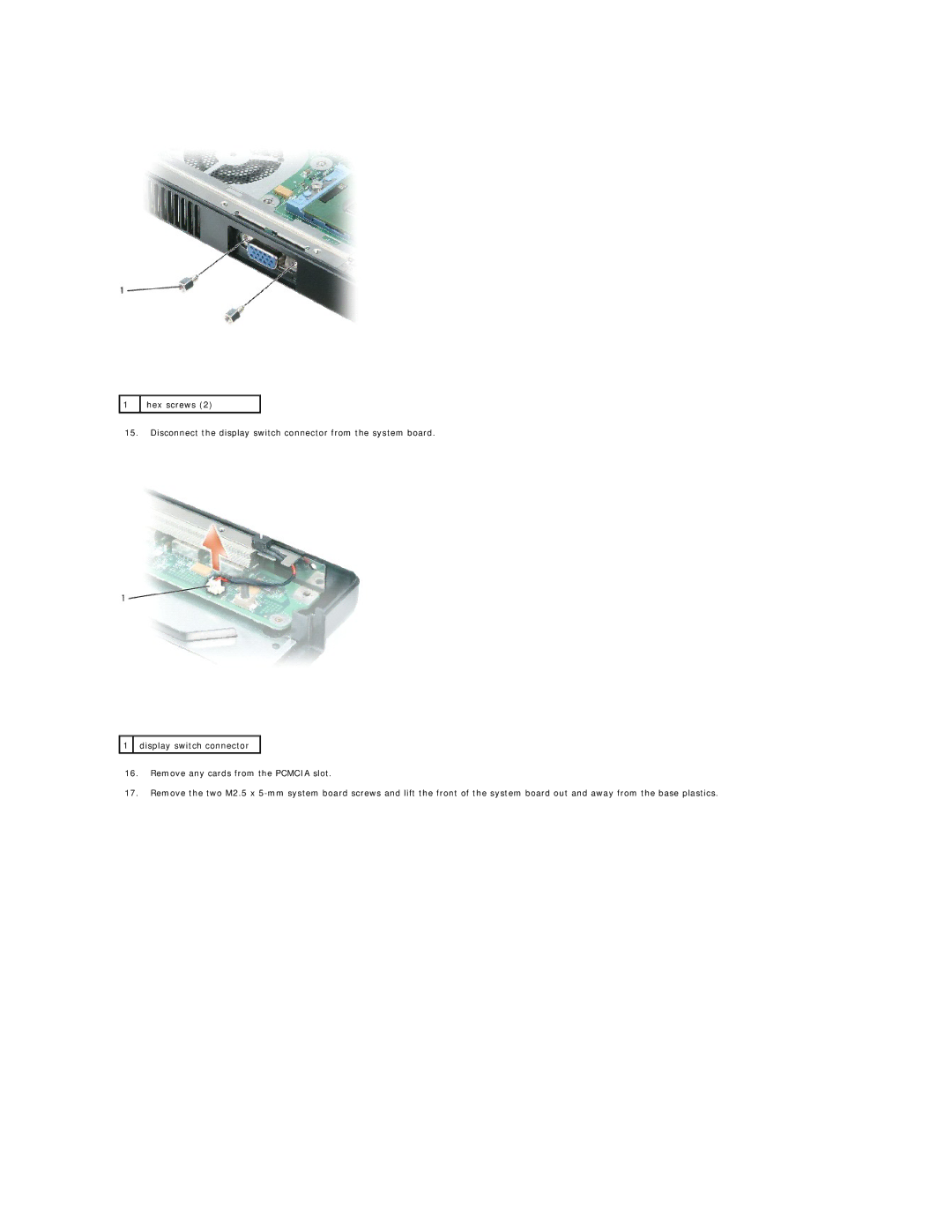
hex screws (2)
15.Disconnect the display switch connector from the system board.
![]() 1
1 ![]() display switch connector
display switch connector
16.Remove any cards from the PCMCIA slot.
17.Remove the two M2.5 x
![]() 1
1
hex screws (2)
15.Disconnect the display switch connector from the system board.
![]() 1
1 ![]() display switch connector
display switch connector
16.Remove any cards from the PCMCIA slot.
17.Remove the two M2.5 x