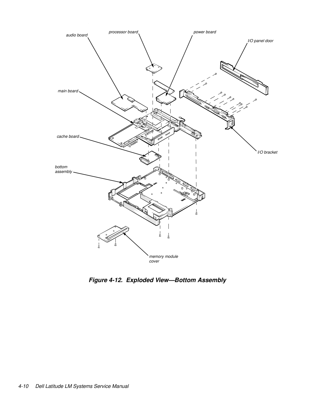
Manuals
/
Brands
/
Computer Equipment
/
Laptop
/
Dell
/
Computer Equipment
/
Laptop
Dell
LM P-133ST
Figure 4-12. Exploded ViewBottom Assembly
1
46
86
86
Download
86 pages, 2.01 Mb
4-10
Dell Latitude LM Systems Service Manual
.
Figure 4-12. Exploded View—Bottom Assembly
main board
power board
audio board
cache board
I/O panel door
I/O bracket
bottom
assembly
memory module
cover
processor board
Contents
Main
Page
Contents
Chapter 1 System Overview. . . . . . . . . . . . . . . . . . . . . . . . . . . . . . . 1-1
Chapter 2 Initial Procedures . . . . . . . . . . . . . . . . . . . . . . . . . . . . . . 2-1
Chapter 3 Beep Codes and Error Messages . . . . . . . . . . . . . . . . . . 3-1
Chapter 4 Removing and Replacing Parts . . . . . . . . . . . . . . . . . . . 4-1
Index Figures
Tables
Page
ead This First
W
arnings, Cautions, and Notes
Page
Page
Chapter 1
System Overview
y
stem Features
1-2 Dell Latitude LM Systems Service Manual
hysical Description
Figure 1-1. Front View of the Portable Computer
Figure 1-2. Back View of the Portable Computer
Status Display
Figure 1-3. Status Display Panel
Keyboard Indicators
CD-ROM/Hard-Disk Drive Indicator
Page
Battery Charge Gauge
assword
ystem Power
Power Conservation
I
nterrupt Assi
nments
Table 1-1. Interrupt Assignments
echnical Specifications
Page
Page
Page
Page
Page
Page
Chapter 2
Initial Procedures
I
nitial User Contact
V
isual Inspection
Page
O
bservin
the Boot Routine
Page
E
G
Page
Page
Table 3-1. POST Beep Codes
ystem Error Messa
es
Page
Page
unnin
the Dell Dia
nostics
Chapter 4
Removin
g
and Replacin
g
Parts
Page
recautionary Measures
Figure 4-3. Main Battery Removal
Figure 4-4. Hard-Disk Drive Removal
Figure 4-5. Options Bay Lock and Latch
Page
Z
IF Connectors
Figure 4-8. Releasing a ZIF Connector
Removing and Replacing Parts 4-7
E
xploded Views of Components and Assemblies
Figure 4-9. Exploded ViewComputer
4-8 Dell Latitude LM Systems Service Manual
Figure 4-10. Exploded ViewLCD Assembly
Removing and Replacing Parts 4-9
.
Figure 4-11. Exploded ViewTop Assembly
4-10 Dell Latitude LM Systems Service Manual
Figure 4-12. Exploded ViewBottom Assembly
F
actory Repair Parts and Assemblies
Page
Page
Page
Page
Page
Table 4-2. Naming Conventions
D
H
ard-Disk Drive
Figure 4-14. Hard-Disk Drive Disassembly
Page
Page
M
emory Module
Figure 4-17. Memory Module Removal
L
CD Assembly
Figure 4-18. LCD Assembly Removal
Front Bezel
Figure 4-19. Front Bezel Removal
LCD Panel
Figure 4-20. LCD Panel Removal
Inverter Board
Figure 4-21. Inverter Board Removal
Microphone
LCD Assembly Latches
Figure 4-22. LCD Assembly Latches Removal
Power/Suspend Indicator
Figure 4-23. Power/Suspend Indicator Removal
Back Bezel
Figure 4-24. Back Bezel Removal
K
eyboard
Figure 4-25. Keyboard Removal
Page
4-32 Dell Latitude LM Systems Service Manual
op Assembly
Production Note!!!
Figure 4-26. Top Assembly Removal
Page
Speakers
Figure 4-27. Speakers Removal
Status Display Board
Figure 4-28. Status Display Board Removal
I/R Device
Figure 4-29. I/R Device Removal
Power Button
Figure 4-30. Power Button Removal
Touch Pad
Figure 4-31. Touch Pad Removal
B
ottom Assembly
Figure 4-32. Bottom Assembly
Processor Board
Figure 4-33. Processor Board Removal
Power Supply Board
Figure 4-34. Power Supply Board Removal
Audio Board
Figure 4-35. Audio Board Removal
Main Board
Figure 4-36. Main Board Removal
Page
Cache Board
Figure 4-37. Cache Board Removal
Page
Index
A
B
C
D
E
F
G
H
I
M
N
O
P
R
T
U
V
Z