LCD Assembly
The LCD assembly consists of the display assembly and its related components. The subsections that follow provide removal and replacement procedures for the components of the LCD assembly.
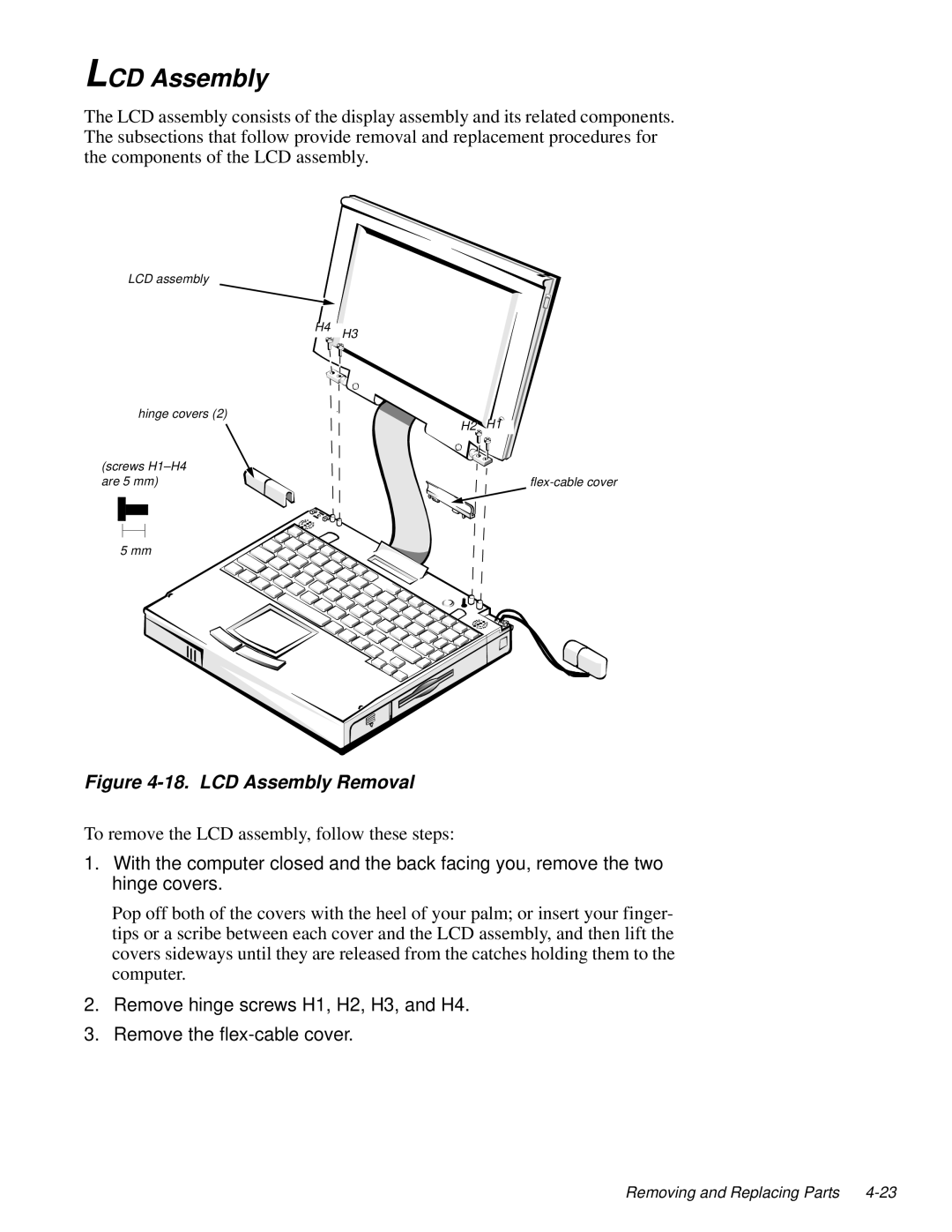
LCD assembly
H4
hinge covers (2)
(screws
H3
H2 H1
5 mm
Figure 4-18. LCD Assembly Removal
To remove the LCD assembly, follow these steps:
1.With the computer closed and the back facing you, remove the two hinge covers.
Pop off both of the covers with the heel of your palm; or insert your finger- tips or a scribe between each cover and the LCD assembly, and then lift the covers sideways until they are released from the catches holding them to the computer.
2.Remove hinge screws H1, H2, H3, and H4.
3.Remove the
Removing and Replacing Parts