2.4.1.3Indicator LEDs
There is an array of LEDs which operate as follows:
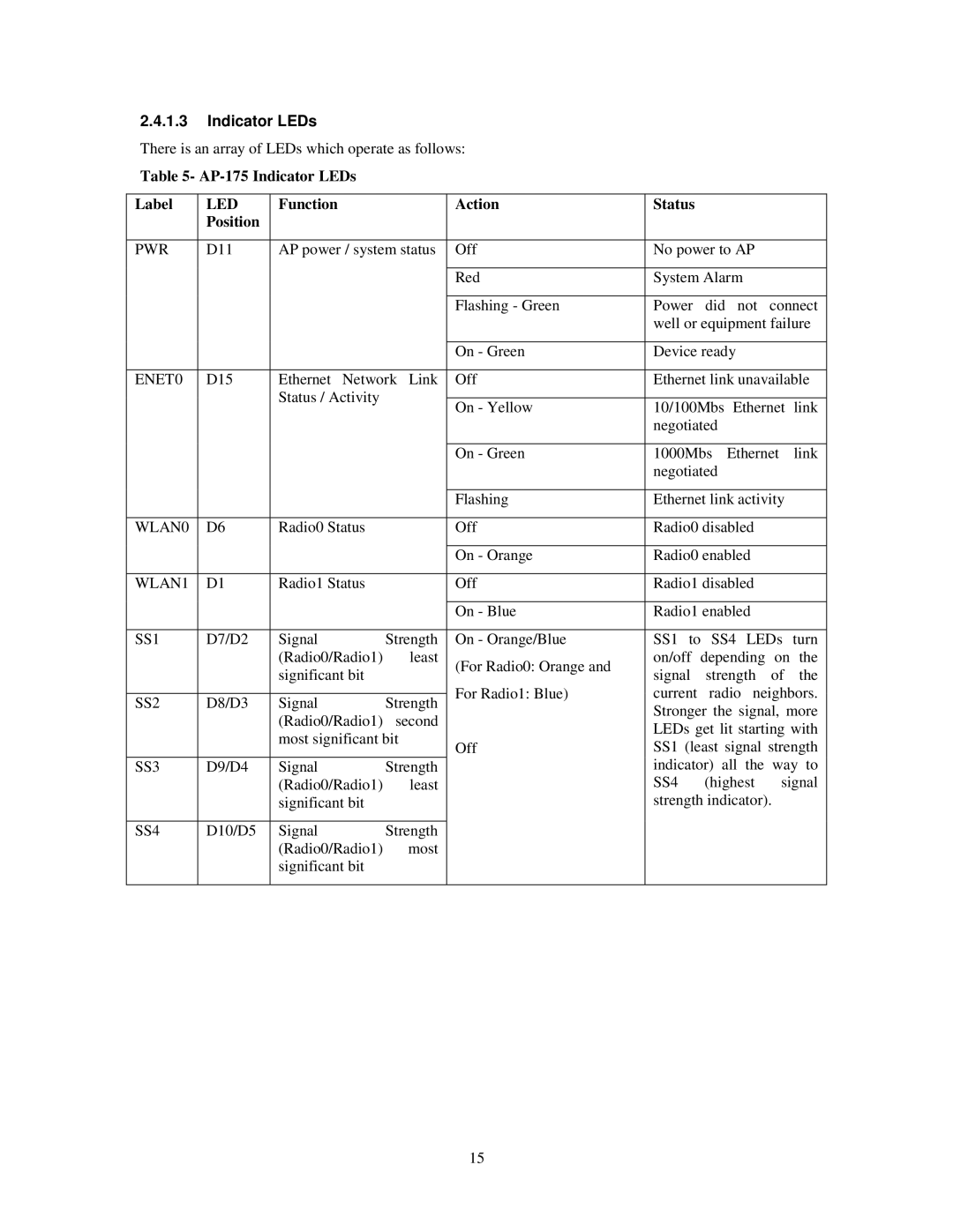
Table 5- AP-175 Indicator LEDs
Label | LED | Function |
| Action | Status |
|
|
|
| |
| Position |
|
|
|
|
|
|
|
| |
|
|
|
|
|
|
| ||||
PWR | D11 | AP power / system status | Off | No power to AP |
|
| ||||
|
|
|
|
|
|
|
| |||
|
|
|
| Red | System Alarm |
|
| |||
|
|
|
|
|
|
|
|
| ||
|
|
|
| Flashing - Green | Power | did | not | connect | ||
|
|
|
|
| well or equipment failure | |||||
|
|
|
|
|
|
|
| |||
|
|
|
| On - Green | Device ready |
|
| |||
|
|
|
|
| ||||||
ENET0 | D15 | Ethernet Network Link | Off | Ethernet link unavailable | ||||||
|
| Status / Activity |
|
|
|
|
|
|
| |
|
|
| On - Yellow | 10/100Mbs | Ethernet | link | ||||
|
|
|
| |||||||
|
|
|
|
| negotiated |
|
|
| ||
|
|
|
|
|
|
|
| |||
|
|
|
| On - Green | 1000Mbs | Ethernet | link | |||
|
|
|
|
| negotiated |
|
|
| ||
|
|
|
|
|
|
| ||||
|
|
|
| Flashing | Ethernet link activity |
| ||||
|
|
|
|
|
|
|
| |||
WLAN0 | D6 | Radio0 Status |
| Off | Radio0 disabled |
|
| |||
|
|
|
|
|
|
|
| |||
|
|
|
| On - Orange | Radio0 enabled |
|
| |||
|
|
|
|
|
|
|
| |||
WLAN1 | D1 | Radio1 Status |
| Off | Radio1 disabled |
|
| |||
|
|
|
|
|
|
|
| |||
|
|
|
| On - Blue | Radio1 enabled |
|
| |||
|
|
|
|
|
| |||||
SS1 | D7/D2 | Signal | Strength | On - Orange/Blue | SS1 to SS4 LEDs turn | |||||
|
| (Radio0/Radio1) | least | (For Radio0: Orange and | on/off | depending | on | the | ||
|
| significant bit |
| signal | strength | of | the | |||
|
|
|
| |||||||
|
|
|
| For Radio1: Blue) | current | radio neighbors. | ||||
SS2 | D8/D3 | Signal | Strength | |||||||
| Stronger the signal, more | |||||||||
|
| (Radio0/Radio1) | second |
| ||||||
|
|
| LEDs get lit starting with | |||||||
|
| most significant bit |
| |||||||
|
| Off | SS1 (least signal strength | |||||||
|
|
|
| |||||||
SS3 | D9/D4 | Signal | Strength |
| indicator) all the way to | |||||
|
| (Radio0/Radio1) | least |
| SS4 | (highest | signal | |||
|
| significant bit |
|
| strength indicator). |
| ||||
|
|
|
|
|
|
|
|
|
| |
SS4 | D10/D5 | Signal | Strength |
|
|
|
|
|
| |
|
| (Radio0/Radio1) | most |
|
|
|
|
|
| |
|
| significant bit |
|
|
|
|
|
|
| |
|
|
|
|
|
|
|
|
|
| |
15