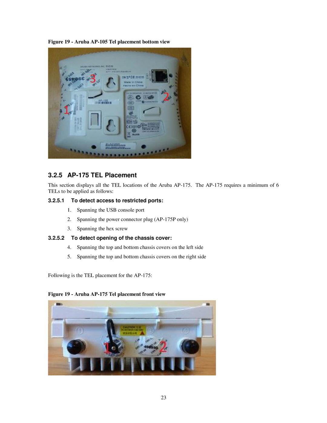
Figure 19 - Aruba AP-105 Tel placement bottom view
3.2.5 AP-175 TEL Placement
This section displays all the TEL locations of the Aruba
3.2.5.1To detect access to restricted ports:
1.Spanning the USB console port
2.Spanning the power connector plug
3.Spanning the hex screw
3.2.5.2To detect opening of the chassis cover:
4.Spanning the top and bottom chassis covers on the left side
5.Spanning the top and bottom chassis covers on the right side
Following is the TEL placement for the
Figure 19 - Aruba AP-175 Tel placement front view
23