Manuals
/
Brands
/
Computer Equipment
/
Network Card
/
Dell
/
Computer Equipment
/
Network Card
Dell
- page 22
Models:
AP-105
AP-175
AP-92
AP-93
W- AP92
W-AP105
W-AP175
W-AP93
1
22
45
45
Download
45 pages, 1.12 Mb
22
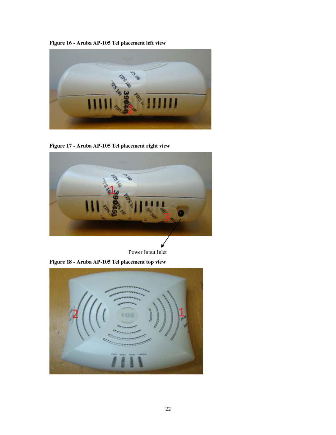
Figure 16 - Aruba AP-105 Tel placement left view
Figure 17 - Aruba AP-105 Tel placement right view
Power Input Inlet
Figure 18 - Aruba AP-105 Tel placement top view
Contents
Main
Page
Page
Page
1 Introduction
1.1 Aruba Dell Relationship
1.2 Acronyms and Abbreviations
Page
2 Product Overview
2.1 AP-92
2.1.1 Physical Description
Page
2.2 AP-93
2.2.1 Physical Description
Page
2.3 AP-105 Series
2.3.1 Physical Description
2.4 AP-175 Series
2.4.1 Physical Description
Page
3 Module Objectives
3.1 Security Levels
3.2 Physical Security
3.2.1 Applying TELs
3.2.2 AP-92 TEL Placement
Page
3.2.3 AP-93 TEL Placement
Page
3.2.4 AP-105 TEL Placement
Page
3.2.5 AP-175 TEL Placement
Page
3.2.6 Inspection/Testing of Physical Security Mechanisms
3.3 Modes of Operation
3.3.1 Configuring Remote AP FIPS Mode
3.3.2 Configuring Control Plane Security (CPSec) protected AP FIPS mode
3.3.3 Configuring Remote Mesh Portal FIPS Mode
3.3.4 Configuring Remote Mesh Point FIPS Mode
3.3.5 Verify that the module is in FIPS mode
3.4 Operational Environment
3.5 Logical Interfaces
4 Roles, Authentication and Services
4.1 Roles
4.1.1 Crypto Officer Authentication
4.1.2 User Authentication
4.1.3 Wireless Client Authentication
4.1.4 Strength of Authentication Mechanisms
Page
4.2 Services
4.2.1 Crypto Officer Services
Description
Service
CSPs Accessed
Service
Description
CSPs Accessed
4.2.2 User Services
Description
Service
CSPs Accessed
Service
Description
Service
CSPs Accessed
4.2.3 Wireless Client Services
CSPs Accessed
4.2.4 Unauthenticated Services
Page
5 Cryptographic Algorithms
6 Critical Security Parameters
Page
Page
Page
7 Self Tests