3.5 Logical Interfaces
The physical interfaces are divided into logical interfaces defined by FIPS
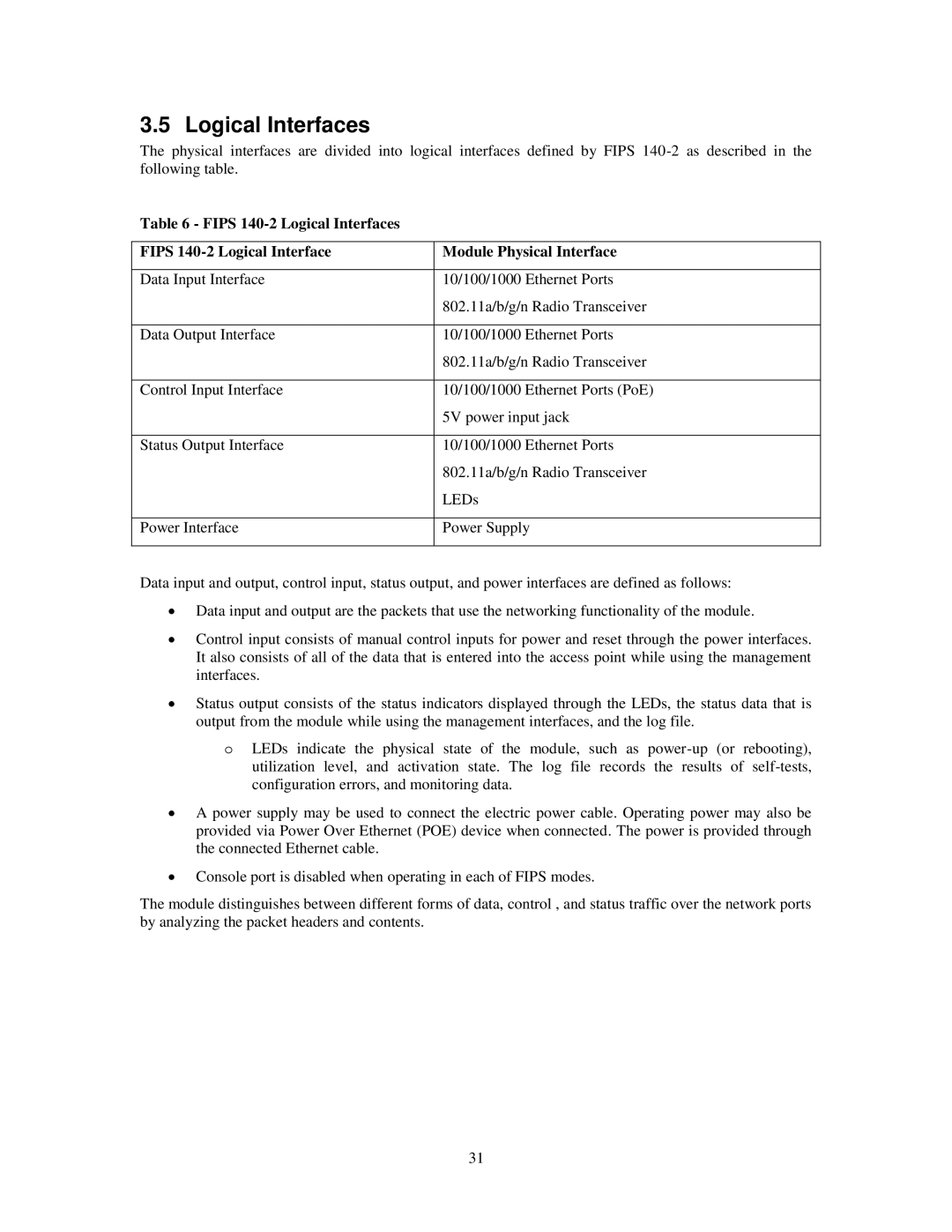
Table 6 - FIPS 140-2 Logical Interfaces
FIPS | Module Physical Interface |
|
|
Data Input Interface | 10/100/1000 Ethernet Ports |
| 802.11a/b/g/n Radio Transceiver |
|
|
Data Output Interface | 10/100/1000 Ethernet Ports |
| 802.11a/b/g/n Radio Transceiver |
|
|
Control Input Interface | 10/100/1000 Ethernet Ports (PoE) |
| 5V power input jack |
|
|
Status Output Interface | 10/100/1000 Ethernet Ports |
| 802.11a/b/g/n Radio Transceiver |
| LEDs |
|
|
Power Interface | Power Supply |
|
|
Data input and output, control input, status output, and power interfaces are defined as follows:
∙Data input and output are the packets that use the networking functionality of the module.
∙Control input consists of manual control inputs for power and reset through the power interfaces. It also consists of all of the data that is entered into the access point while using the management interfaces.
∙Status output consists of the status indicators displayed through the LEDs, the status data that is output from the module while using the management interfaces, and the log file.
oLEDs indicate the physical state of the module, such as
∙A power supply may be used to connect the electric power cable. Operating power may also be provided via Power Over Ethernet (POE) device when connected. The power is provided through the connected Ethernet cable.
∙Console port is disabled when operating in each of FIPS modes.
The module distinguishes between different forms of data, control , and status traffic over the network ports by analyzing the packet headers and contents.
31