Zzzghoofrp
865·6*8
Page
KHQ8VLQJRXU&RPSXWHU6\VWHP
6DIHW\,QVWUXFWLRQV
$51,1*,PSURSHURUSURORQJHGNH\ERDUGXVHPD\UHVXOWLQLQMXU\
UJRQRPLF&RPSXWLQJ+DELWV
IROORZLQVWDOODWLRQDQGVHUYLFHLQVWUXFWLRQVFORVHO\
KHQRUNLQJ,QVLGHRXU&RPSXWHU
7XUQRII\RXUFRPSXWHUDQGDQ\SHULSKHUDOV
Doing so reduces the potential for personal injury or shock
3URWHFWLQJ$JDLQVWOHFWURVWDWLFLVFKDUJH
Lqvwuxfwlrqvdwwkhiurqwriwklvjxlgh
Page
$ERXW7KLV*XLGH
3UHIDFH
DUUDQW\DQG5HWXUQ3ROLF\,QIRUPDWLRQ
2WKHURFXPHQWVRX0D\1HHG
1RWDWLRQDO&RQYHQWLRQV
DUQLQJV&DXWLRQVDQG1RWHV
\SRJUDSKLFDO&RQYHQWLRQV
1RERRWGHYLFHDYDLODEOH
Example del drive path filename /p
Kdswhu
Rqwhqwv
NIC
Acpi
Scsi
Xviii
$SSHQGL%
$SSHQGL$
ICU Error Messages Configuration Manager Messages
$SSHQGL
ESD
ORVVDU\ QGH Ljxuhv
Xxii
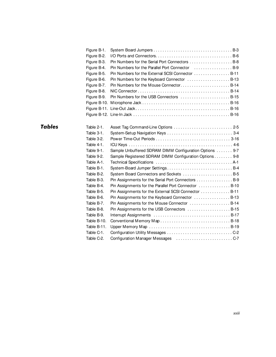
7DEOHV
Xxiv
\VWHPHDWXUHV
Qwurgxfwlrq
2HOO3UHFLVLRQHVNWRS6\VWHPV8VHUV*XLGH
Introduction
4HOO3UHFLVLRQHVNWRS6\VWHPV8VHUV*XLGH
LJXUHHOO,QVSHFWRU3URJUDP
6HOO3UHFLVLRQHVNWRS6\VWHPV8VHUV*XLGH
5HLQVWDOOLQJLQGRZV17
5HLQVWDOOLQJLQGRZV
QWHO3,,,18SGDWH,QVWDOOHUIRULQGRZV
LJXUHURQW3DQHO
URQW3DQHO
Rqqhfwlqjwhuqdohylfhv
DFN3DQHO
6HFXULW\&DEOH6ORWDQG3DGORFN5LQJ
10HOO3UHFLVLRQHVNWRS6\VWHPV8VHUV*XLGH
LJXUH6HFXULW\&DEOH6ORWDQG3DGORFN5LQJ
HWWLQJ+HOS
12HOO3UHFLVLRQHVNWRS6\VWHPV8VHUV*XLGH
8VLQJWKH6RIWZDUH6XSSRUW 8WLOLWLHV
HOO,QVWDOOHG6RIWZDUH6XSSRUW8WLOLWLHV
\VWHP8WLOLWLHVDQG6HUYLFHV
Rshqgrfxphqwvrudssolfdwlrqsurjudpv
Kdugglvngulyh
Glvnhwwh
Vhuylfhv
5HPRYLQJD6HUYLFH
To remove a service, perform the following steps
$VVHW7DJ8WLOLW\
Wkhvhuylfhv
$VVLJQLQJDQGHOHWLQJDQ$VVHW7DJ1XPEHU
HOO$XWR6KXWGRZQ6HUYLFH
$VVLJQLQJDQGHOHWLQJDQ2ZQHU7DJ
7DEOH$VVHW7DJ&RPPDQG/LQH2SWLRQV
HOO7KHUPDO6KXWGRZQ6HUYLFH
+RZ$XWR6KXWGRZQRUNV
IRXU2SHUDWLQJ6\VWHP/RFNV8S
$XWR3RZHU2Q8WLOLW\
Autopowr /off command turns off your computer
QVWDOOLQJWKH$XWR3RZHU2Q8WLOLW\
Dxwrsrzu Lihuuruohyhojrwrdodup Lihuuruohyhojrwrexwwrq Dodup
Ulyhu
XV0DVWHULQJ,ULYHUV
5HLQVWDOOLQJWKHLQGRZV17%XV0DVWHULQJ
Uhpryhwkhroghugulyhuehiruhlqvwdoolqjwkhqhzgulyhu
Click New to install the new driver
5HPRYLQJWKHLQGRZV17%XV0DVWHULQJ,ULYHU
GLUHFWRU\IURPZKLFKWRLQVWDOOWKHGULYHULVOLVWHG
KHQDVNHGLI\RXDUHVXUH\RXZDQWWRUHPRYHWKHGULYHUFOLFNHV
QDEOLQJWKHLQGRZV%XV0DVWHULQJ,ULYHU
8VLQJWKH6\VWHP6HWXS3URJUDP
QWHULQJWKH6\VWHP6HWXS3URJUDP
\VWHP6HWXS6FUHHQV
5HVWDUW\RXUV\VWHP
Using the System Setup Program
8VLQJWKH6\VWHP6HWXS3URJUDP
7DEOH6\VWHP6HWXS1DYLJDWLRQ.H\V
Moves to the next field
LJXUH6\VWHP6HWXS6FUHHQV
Configuration options Title box Help
7LPH
\VWHP6HWXS2SWLRQV
DWH
LVNHWWHULYH$DQGLVNHWWHULYH%
HYLFHV2WKHU7KDQ+DUGLVNULYHV
ULYHV3ULPDU\DQG6HFRQGDU\
IRX+DYHD3UREOHP
IRX.QRZWKHULYH7\SH1XPEHU
IRXR1RW.QRZWKHULYH7\SH1XPEHU
386SHHG
5HVHUYHG0HPRU\
7KHUPDO3RZHU2II
KDVVLV,QWUXVLRQ
\ERDUGUURUV
$OHUW&RYHUZDVSUHYLRXVO\UHPRYHG
\VWHP3DVVZRUG
3DVVZRUG6WDWXV
3DVVZRUGORFNHGQRWGLVDEOHG
Lvnhwwhluvw
RRW6HTXHQFH
+DUGLVN2QO\
HYLFH/LVW
PgDn next PgUp prev
LJXUH6DPSOHHYLFH/LVW6FUHHQ
6HWXS3DVVZRUG
$XWR3RZHU2Q
14HOO3UHFLVLRQHVNWRS6\VWHPV8VHUV*XLGH
3RZHU0DQDJHPHQW
6DYLQJ0RQLWRU3RZHU
Ulvngdpdjlqjwkhprqlwru
6DYLQJ,+DUGLVNULYH3RZHU
Disabled Never Maximum Minutes Hour Regular Minimum
7DEOH3RZHU7LPH2XW3HULRGV
16HOO3UHFLVLRQHVNWRS6\VWHPV8VHUV*XLGH
6RXQG
0RXVH
6HULDO3RUWDQG6HULDO3RUW
3DUDOOHO0RGH
3DUDOOHO3RUW
Lvnhwwh
18HOO3UHFLVLRQHVNWRS6\VWHPV8VHUV*XLGH
6SHDNHU
\VWHPDWD
6WDUWWKHLQGRZVRULQGRZV17RSHUDWLQJV\VWHP
8VLQJWKH6\VWHP3DVVZRUGHDWXUH
$VVLJQLQJD6\VWHP3DVVZRUG
20HOO3UHFLVLRQHVNWRS6\VWHPV8VHUV*XLGH
9HULI\WKDW3DVVZRUG6WDWXVLVVHWWR8QORFNHG
3UHVVWKHOHIWRUULJKWDUURZNH\
\SHWKHQHZV\VWHPSDVVZRUG
8VLQJRXU6\VWHP3DVVZRUGWR6HFXUHRXU6\VWHP
8VLQJWKH6HWXS3DVVZRUGHDWXUH
HOHWLQJRU&KDQJLQJDQLVWLQJ6\VWHP3DVVZRUG
KHQSURPSWHGW\SHWKHV\VWHPSDVVZRUG
2SHUDWLQJLWKD6HWXS3DVVZRUGQDEOHG
$VVLJQLQJD6HWXS3DVVZRUG
HOHWLQJRU&KDQJLQJDQLVWLQJ6HWXS3DVVZRUG
QWHUWKH6\VWHP6HWXSSURJUDP
5HSODFHWKHFRPSXWHUFRYHU
LVDEOLQJDRUJRWWHQ3DVVZRUG
5HSHDWVWHS 5HSODFHWKH36MXPSHUSOXJWKHHQDEOHVHWWLQJ
$VVLJQDQHZV\VWHPDQGRUVHWXSSDVVZRUG
26HOO3UHFLVLRQHVNWRS6\VWHPV8VHUV*XLGH
5HVSRQGLQJWRUURU0HVVDJHV
8VLQJWKH,6$&RQILJXUDWLRQ8WLOLW\
HWHUPLQHZKHWKHU\RXQHHGWRUXQWKH,&8
4XLFN6WDUW
6WDUWWKHV\VWHPXVLQJ\RXU,&8GLVNHWWH
Ghylfh
8DWDEDVH
$ERXWWKH,&8
DFNLQJ8SWKH,&8 Lvnhwwh
3UHSDULQJWR8VHWKH,&8
6WDUWLQJWKH,&8
$FFHVVLQJ+HOS
0DNLQJ6HOHFWLRQVLQWKH,&8
LJXUH$GG1HWZRUN&DUGLDORJ%R
$GGLQJD/LVWHG&DUG
Fkdswhu
6HOHFWWKHQDPHRIWKHFDUG\RXZDQWWRDGG
LJXUH&DUG&RQILJXUDWLRQLDORJ%R
7RVHOHFWWKHUHVRXUFHV\RXUVHOIFOLFN$GYDQFHG
VHWWLQJDQGWKHQFOLFN6HWWLQJV
LJXUH$YDLODEOH6HWWLQJV/LVW%R
Lvkhgvhohfwlqjuhvrxufhviruwkhixqfwlrq
$GGLQJDQ8QOLVWHG&DUG
LJXUH6SHFLI\,QWHUUXSW/LVW%R
LJXUH6SHFLI\,QWHUUXSWLDORJ%R
\RXKDGWRDVVLJQDGLVDOORZHGUHVRXUFHYDOXHWRWKHFDUGLQVWHSV
0RGLI\LQJD&DUG
You have completed this procedure do not proceed to step
Zlqgrz
UHVSHFWLYHO\
9LHZLQJ5HVRXUFHV
Rshudwlrq
ICU returns to the ICU window
LWLQJWKH,&8
6DYLQJWKH6\VWHP&RQILJXUDWLRQ
LJXUH6\VWHP5HVRXUFH8VDJHLDORJ%R
LJXUH&DUG5HVRXUFH8VDJHLDORJ%R
RFNLQJDQG8QORFNLQJ$OO5HVRXUFHV
RFNLQJDQG8QORFNLQJ&DUGV
OLFN0RGLI\RUVHOHFW0RGLI\&DUGIURPWKH&RQILJXUHPHQX
RFNLQJDQG8QORFNLQJ&RQILJXUDWLRQ5HVRXUFHV
OLFN6HWWLQJV
6HOHFW/RFN5HVRXUFHV
Rqwuroohu
LJXUH1,&&RQQHFWRUDQG,QGLFDWRUV
RQQHFWLQJWRD1HWZRUN
RQQHFWWKHQHWZRUNFDEOHWRWKHEDFNRI\RXUFRPSXWHU
RQILJXUHWKH1,&DQGLQVWDOOWKHQHWZRUNGULYHU
6HWWLQJWKH1HWZRUNUDPH7\SH
1HWZRUN&DEOH5HTXLUHPHQWV
Select OEM Option dialog box appears
RQILJXULQJWKH1
See your network administrator for information
HOO,QVWDOOHGLQGRZV6HUYLFH5HOHDVH
Qhwzrun
6WDUWWKHLQGRZVRSHUDWLQJV\VWHP
Contact your network administrator for information
Zrundffhvv
LQGRZV2SHUDWLQJ6\VWHPV1RW,QVWDOOHGE\HOO
OLFN2.LQWKH,QVHUWLVNGLDORJER
8VLQJ&RPWKHULVN/9HUVLRQLVNHWWHV
QVWDOOWKHLQGRZV1,&GULYHU
Zrunzlqgrz OLFN2.DQGWKHQFOLFNHVWRUHVWDUW\RXUV\VWHP
10HOO3UHFLVLRQHVNWRS6\VWHPV8VHUV*XLGH
LJXUH$XGLR&RQQHFWRUV
RQQHFWLQJ$XGLRHYLFHV
0LFURSKRQHV
6SHDNHUV
5HFRUG3OD\EDFNHYLFHV
QVWDOOWKH&520GULYHLQ\RXUFRPSXWHU
$GMXVWLQJ9ROXPHLQLQGRZV
$GMXVWLQJ9ROXPH
$GMXVWLQJ9ROXPHLQLQGRZV17
RXEOHFOLFNWKH0XOWLPHGLDLFRQ
8VLQJ$XGLR8WLOLWLHV
$GMXVWLQJ6RXQG
0XWLQJWKH,QWHUQDO6SHDNHU
Wdvnedu
QVWDOOLQJ$XGLRULYHUV
$XGLRULYHUVIRULQGRZV
$WWKHFRS\LQJILOHVZLQGRZW\SHD? DQGFOLFN2
$XGLRULYHUVIRULQGRZV17
Glvngulyh 6WDUWWKHLQGRZV17RSHUDWLQJV\VWHP
QWKH,QVWDOOULYHUGLDORJERW\SHD?DQGFOLFN2
8VLQJWKH,QWHJUDWHG6&6 Rqwuroohuv
QVWDOOLQJ6&6,ULYHUV
HYLFH&RQVLGHUDWLRQV
QVWDOOLQJ6&6,ULYHUVIRULQGRZV
LJXUH,QWHUQDOULYH%D\V
ULYHUIRUWKH6HFRQGDU\6&6,&RQWUROOHU
ULYHUIRUWKH3ULPDU\6&6,&RQWUROOHU
Gulyh 6WDUWWKHLQGRZVRSHUDWLQJV\VWHP
$WWKH&RS\LQJLOHVZLQGRZW\SHD?DQGFOLFN2
RXEOHFOLFNWKH6\VWHPLFRQ OLFNWKHHYLFH0DQDJHUWDE
RXEOHFOLFN$GDSWHF$,&3&,6&6,&RQWUROOHU
Gulyh 6WDUWWKHLQGRZV17RSHUDWLQJV\VWHP
Follow these steps to install Scsi drivers for Windows NT
QVWDOOLQJ6&6,ULYHUVXULQJLQGRZV17 Qvwdoodwlrq
Lqvwdoodwlrq
6HOO3UHFLVLRQHVNWRS6\VWHPV8VHUV*XLGH
HIRUHRX%HJLQ
6DIHW\LUVW³RURXDQGRXU&RPSXWHU
Wkhvhtxhqfhlqglfdwhg 7XUQRII\RXUFRPSXWHUDQGDOOSHULSKHUDOV
Use the following procedure to remove the computer cover
5HPRYLQJWKH&RPSXWHU&RYHU
8QSDFNLQJRXU+DUGZDUH2SWLRQ
LJXUH3DGORFN,QVWDOOHG
LJXUH5HPRYLQJWKH&RPSXWHU&RYHU
5HPRYHWKHFRYHU
5HSODFLQJWKH&RPSXWHU&RYHU
Use the following procedure to replace the computer cover
LJXUH5HSODFLQJWKH&RPSXWHU&RYHU
LQVLGHWKHFRPSXWHU·VFKDVVLV 5HSODFHWKHFRYHU
See , Using the System Setup Program, for instructions
QVLGHRXU&RPSXWHU
LJXUH&RPSXWHU2ULHQWDWLRQ9LHZ
LJXUH,QVLGHWKH&KDVVLV
LJXUH5RWDWLQJWKH3RZHU6XSSO\
5RWDWLQJWKH3RZHU6XSSO\$ZD\URPWKH 6\VWHP%RDUG
8HOO3UHFLVLRQHVNWRS6\VWHPV8VHUV*XLGH
QVWDOOLQJ6\VWHP%RDUG2SWLRQV
SDQVLRQ&DUGV
Use -1 to locate the system board features
LJXUHSDQVLRQ&DUGV
SDQVLRQ6ORWV
See , Using the ISA Configuration Utility, for instructions
Follow this general procedure to install an expansion card
QVWDOOLQJDQSDQVLRQ&DUG
LJXUH5HPRYLQJWKHLOOHU%UDFNHW
LJXUH,QVWDOOLQJDQSDQVLRQ&DUG
RQQHFWDQ\FDEOHVWKDWVKRXOGEHDWWDFKHGWRWKHFDUG
$/57&RYHUZDVSUHYLRXVO\UHPRYHG
Follow this general procedure to remove an expansion card
$GGLQJ0HPRU\
5HPRYLQJDQSDQVLRQ&DUG
00,QVWDOODWLRQ*XLGHOLQHV
7DEOH6DPSOH8QEXIIHUHG65$0,00&RQILJXUDWLRQ2SWLRQV
64 MB 32 MB 96 MB 128 MB 192 MB 256 MB 384 MB 512 MB
Wrwdo
7DEOH6DPSOH5HJLVWHUHG65$0,00&RQILJXUDWLRQ2SWLRQV
QVWDOOLQJD,00
0LFURSURFHVVRU8SJUDGHV
5HPRYLQJD,00
Iluvwsurfhvvru
FDUWULGJHKHDWVLQNDVVHPEO\IURPLWVFRQQHFWRU
$GGLQJRU5HSODFLQJD0LFURSURFHVVRU
Frqqhfwru
LJXUH6&&DUWULGJH+HDW6LQN$VVHPEO\5HPRYDO
See , Using the System Setup Program
Vhfxulqjwdevqdsvlqwrsodfh
DWLQJFRUUHFWO\
5HSODFLQJWKH6\VWHP%DWWHU\
LJXUH6\VWHP%DWWHU\DQG%DWWHU\6RFNHW
RFDWHWKHEDWWHU\DQGUHPRYHLW
QVWDOOWKHQHZEDWWHU\
7XUQRII\RXUFRPSXWHUDQGXQSOXJLWIRUDWOHDVWPLQXWHV
See , Using the System Setup Program for instructions
Qvwdoolqjulyhv
10-2HOO3UHFLVLRQHVNWRS6\VWHPV8VHUV*XLGH
LJXUHULYH/RFDWLRQV
LJXUH&3RZHU&DEOH&RQQHFWRU
Rqqhfwlqjulyhv
10-4HOO3UHFLVLRQHVNWRS6\VWHPV8VHUV*XLGH
LJXUHULYH,QWHUIDFH&RQQHFWRUV
8QSDFNWKHGULYHDQGSUHSDUHLWIRULQVWDOODWLRQ
QVWDOOLQJDULYHLQD,QFKULYH%D\
$WWDFKWKHEUDFNHWWRWKHQHZGULYH
LJXUH5HPRYLQJDULYH
See Installing an Expansion Card in Chapter
LJXUH,QVHUWLQJWKH1HZULYH,QWRWKHULYH%D\
Frqwuroohufduglqdqhsdqvlrqvorw
LJXUH$WWDFKLQJ,7DSHULYH&DEOHV
Sdqholqvhuwiurpwkhiurqwfryhu
10-8HOO3UHFLVLRQHVNWRS6\VWHPV8VHUV*XLGH
QVWDOOLQJDQ,+DUGLVNULYH
8SGDWH\RXUV\VWHPFRQILJXUDWLRQLQIRUPDWLRQ
9HULI\WKDW\RXUV\VWHPZRUNVFRUUHFWO\
QVWDOOLQJDQ,+DUGLVNULYHLQWKH+DUGLVN ULYH%UDFNHW
ULYH$GGUHVVLQJ
Wklvsurfhgxuh 3UHSDUHWKHGULYHIRULQVWDOODWLRQ
10-10HOO3UHFLVLRQHVNWRS6\VWHPV8VHUV*XLGH
5HPRYHWKHGULYHEUDFNHWIURPWKHFKDVVLV
LJXUH5HPRYLQJWKH+DUGLVNULYH%UDFNHW
Udfnhw
LJXUH,QVHUWLQJD,QFK+DUGLVNULYH,QWRWKH
10-12HOO3UHFLVLRQHVNWRS6\VWHPV8VHUV*XLGH
Ljxuh
Kdvvlv
LJXUH$WWDFKLQJ+DUGLVNULYH&DEOHV
See Drives Primary and Secondary in Chapter
10-14HOO3UHFLVLRQHVNWRS6\VWHPV8VHUV*XLGH
QVWDOOLQJ6&6,HYLFHV
RQILJXUDWLRQ*XLGHOLQHV
QVWDOO\RXURSHUDWLQJV\VWHPRQWKHKDUGGLVNGULYH
10-16HOO3UHFLVLRQHVNWRS6\VWHPV8VHUV*XLGH
HYLFH7HUPLQDWLRQ
HQHUDO3URFHGXUHIRU,QVWDOOLQJ6&6,HYLFHV
Deohv
QVWDOOWKH6&6,GHYLFHVDVDSSURSULDWH
8QSDFNHDFK6&6,GHYLFHDQGSUHSDUHLWIRULQVWDOODWLRQ
$WWDFKWKH6&6,FDEOHWRHDFK6&6,GHYLFH
10-18HOO3UHFLVLRQHVNWRS6\VWHPV8VHUV*XLGH
RQQHFWWKH6&6,GHYLFHVWRDSRZHUVRXUFH
10-20HOO3UHFLVLRQHVNWRS6\VWHPV8VHUV*XLGH
3DUWLWLRQLQJDQGRUPDWWLQJ6&6,+DUGLVNULYHV
7DEOH$7HFKQLFDO6SHFLILFDWLRQV
7HFKQLFDO6SHFLILFDWLRQV
7DEOH$7HFKQLFDO6SHFLILFDWLRQVFRQWLQXHG
Externally accessible Serial DTE
64 MB 1024 MB F0000000h-F000FFFFh
Audio line Audio line out Audio microphone
Control panel connectors
Internally accessible
Hard-disk drive access indicator . . . . . . . . green LED
Diskette drive CD-ROM drive audio interface Wakeup On LAN
RQWUROVDQG,QGLFDWRUVFRQWLQXHG
Qylurqphqwdofrqwlqxhg
Xpshuv
XPSHUVDQG6ZLWFKHV³$*HQHUDO Sodqdwlrq
6ZLWFKHV
LJXUH%6\VWHP%RDUG-XPSHUV
7DEOH%6\VWHP%RDUG-XPSHU6HWWLQJV
7DEOH%6\VWHP%RDUG&RQQHFWRUVDQG6RFNHWV
\VWHP%RDUG/DEHOV
23RUWVDQG&RQQHFWRUV
$GGLQJDQSDQVLRQ&DUG&RQWDLQLQJ6HULDORU3DUDOOHO3RUWV
6HULDODQG3DUDOOHO3RUWV
LJXUH%3LQ1XPEHUVIRUWKH6HULDO3RUW&RQQHFWRUV
6HULDO3RUW&RQQHFWRUV
3DUDOOHO3RUW&RQQHFWRU
WHUQDO6&6,&RQQHFWRU
Trmpwr
LJXUH%3LQ1XPEHUVIRUWKHWHUQDO6&6,&RQQHFWRU
Rsvd
Dparh
\ERDUG&RQQHFWRU
\ERDUGDQG0RXVH&RQQHFWRUV
0RXVH&RQQHFWRU
Kbdata
Kbclk
Rqqhfwru
9LGHR&RQQHFWRU
Mfdata
Mfclk
0LFURSKRQH-DFN
86%&RQQHFWRUV
Ghylfhviruwkhlupdlpxpfxuuhqwudwlqjv
Data
LQH2XW-DFN
QWHUUXSW$VVLJQPHQWV
LQH,Q-DFN
LJXUH%0LFURSKRQH-DFN
7DEOH%,QWHUUXSW$VVLJQPHQWV
0HPRU\$OORFDWLRQV
7DEOH%&RQYHQWLRQDO0HPRU\0DS
0010FFF0-3FFFFFFF
FFFC0000-FFFFFFFF Bios ROM
Extended memory
Fffbffff Reserved
20HOO3UHFLVLRQHVNWRS6\VWHPV8VHUV*XLGH
8UURU0HVVDJHV
$&RQILJXUDWLRQ8WLOLW\ 0HVVDJHV
7DEOH&&RQILJXUDWLRQ8WLOLW\0HVVDJHV
7DEOH&&RQILJXUDWLRQ8WLOLW\0HVVDJHVFRQWLQXHG
Wrsurfhhg
FDWHJRU\FDUG3UHVV2
Dgghg
Fdqehdgghg
Frqiolfwlqjbfdug
7KH,&8GHWHFWV
ILOHXVHGE\WKH,&8IRU
7KHFRQILJXUDWLRQFIJ
Zlvkwrordgwkhiloh
1RFRQILJXUDWLRQFIJ
7DEOH&&RQILJXUDWLRQ0DQDJHU0HVVDJHV
RQILJXUDWLRQ0DQDJHU0HVVDJHV
7DEOH&&RQILJXUDWLRQ0DQDJHU0HVVDJHVFRQWLQXHG
See Modifying a Card in for instructions
Frqwlqxh
3OD\&DUG1DPH
FRQILJXUH3OXJDQG
FRQILJXUH3&,GHYLFH
Dlohgwrfrqiljxuh
DWD3UHVHUYDWLRQ
6FKHGXOLQJ%DFNXSV
Dfnxshylfhv
5HFRYHULQJDWD
OHDQLQJ6\VWHP&RPSRQHQWV
Dqgglvfrqqhfwwkhpiurpwkhlusrzhuvrxufhv
5HFRPPHQGHG7RROVDQG$FFHVVRULHV
Page
+XPLGLW\
$OWLWXGH
XVWDQG3DUWLFOHV
OHFWURPDJQHWLFDQG5DGLRUHTXHQF\,QWHUIHUHQFH
Ruurvlrq
6KRFNDQG9LEUDWLRQ
0DJQHWLVP
3RZHU6RXUFH,QWHUUXSWLRQV
6XUJH3URWHFWRUV
3RZHU3URWHFWLRQHYLFHV
LQH&RQGLWLRQHUV
8QLQWHUUXSWLEOH3RZHU6XSSOLHV
10HOO3UHFLVLRQHVNWRS6\VWHPV8VHUV*XLGH
ODVV$
5HJXODWRU\1RWLFHV
ODVV%
RPSOLDQFH&HFK5HSXEOLF 2QO\
1RWLFH&DQDGD2QO\
Uhtxluhgwrwdnhdghtxdwhphdvxuhv
1RWLFH
RUHDQ5HJXODWRU\1RWLFH
ODVV$HYLFH
ODVV%HYLFH
8ZNBHBOJB1PMTLJFHP$FOUSVN#BEBËJ $FSUZGJLBDKJ
1PPTUBFJOTUSVLDKFCFQJFDFËTUXB
3ROLVK&HQWHUIRU7HVWLQJDQG&HUWLILFDWLRQ 1RWLFH
Importer Dell Computer de México De C.V
Round Rock, TX
Col. Cuauhtemoc
16500 México, D.F
Importador Dell Computer de México De C.V
RYHUDJHXULQJHDU2QH
LPLWHG7KUHHHDUDUUDQW\86DQG &DQDGD2QO\
Hqhudo
RYHUDJHXULQJHDUV7ZRDQG7KUHH
´7RWDO6DWLVIDFWLRQµ5HWXUQ3ROLF\86DQG &DQDGD2QO\
4HOO3UHFLVLRQHVNWRS6\VWHPV8VHUV*XLGH
Dgdswhufdug
Dssolfdwlrqsurjudp
Dvvhwwdjfrgh
Dxwrhhfedwiloh
Dwwulexwh
Edfnxs
EDFNXSEDWWHU\
ESL
Errwdeohglvnhwwh
ESV
EXV
FRQYHQWLRQDOPHPRU\
Frqwurosdqho
Frsurfhvvru
FSL
GSL
Abbreviation for digital signal processing
Abbreviation for dots per inch 306
GULYHW\SHQXPEHU
Hsdqvlrqexv
HSDQGHGPHPRU\
Hsdqvlrqfdugfrqqhfwru
HWHQGHGPHPRU\
Judsklfvprgh
Judsklfvfrsurfhvvru
Jurxs
Khdwvlqn
Elwv
Mxpshu
Elwvvhf
NH\FRPELQDWLRQ
0ESV
Pdwkfrsurfhvvru
PHPRU\
PHPRU\DGGUHVV
Prxvh
Prghp
PXOWLIUHTXHQF\PRQLWRU
Qrqlqwhuodfhg
Slho
Shulskhudoghylfh
3OXJDQG3OD\
SSP
Uhdgphiloh
UHDGRQO\ILOH
Uhdoprgh
Uhiuhvkudwh
Vhuldosruw
VHF
Vhuylfhwdjqxpehu
Vkdgrzlqj
‡ RAM
\VWHPERDUG
\VWHPGLVNHWWH
\VWHPPHPRU\
XWLOLW\
XSSHUPHPRU\DUHD
$IHDWXUHFRQQHFWRU
Ylghrdgdswhu
YLGHRPHPRU\
Ylghrgulyhu
Ylghrprgh
Ylghruhvroxwlrq
Lqgrzv
Zlqlqliloh
LQGRZV17
Zulwhsurwhfwhg
Dell Precision 410 Desktop Systems User’s Guide
QGH
DMI
Device List setting Diagnosing problems
Eide hard-disk drives addressing
Expansion slots about
Keyboard Errors option
Pin assignments, B-14 pin numbers, B-14
Parallel Port option Partitioning
Pin assignments, B-9, B-11 pin numbers, B-8,B-11
Synchronous dynamic random-access memory. See Sdram
Pin assignments, B-15 pin numbers, B-15