ASSEMBLING
STOCK STOP TO TABLE
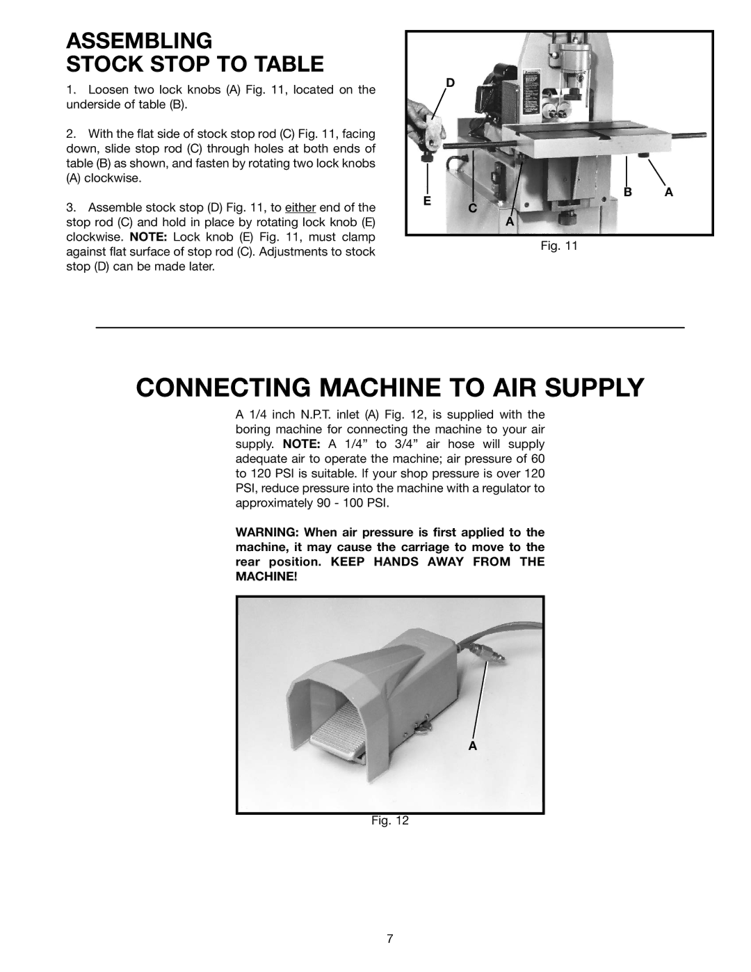
1. | Loosen two lock knobs (A) Fig. 11, located on the |
underside of table (B). | |
2. | With the flat side of stock stop rod (C) Fig. 11, facing |
down, slide stop rod (C) through holes at both ends of | |
table (B) as shown, and fasten by rotating two lock knobs | |
(A) clockwise. | |
D
E
B A
3. Assemble stock stop (D) Fig. 11, to either end of the |
stop rod (C) and hold in place by rotating lock knob (E) |
clockwise. NOTE: Lock knob (E) Fig. 11, must clamp |
against flat surface of stop rod (C). Adjustments to stock |
stop (D) can be made later. |
C
A
Fig. 11
CONNECTING MACHINE TO AIR SUPPLY
A 1/4 inch N.P.T. inlet (A) Fig. 12, is supplied with the boring machine for connecting the machine to your air supply. NOTE: A 1/4” to 3/4” air hose will supply adequate air to operate the machine; air pressure of 60 to 120 PSI is suitable. If your shop pressure is over 120 PSI, reduce pressure into the machine with a regulator to approximately 90 - 100 PSI.
WARNING: When air pressure is first applied to the machine, it may cause the carriage to move to the rear position. KEEP HANDS AWAY FROM THE MACHINE!
A
Fig. 12
7
