GUIDE RAILS AND
SWITCH ASSEMBLY
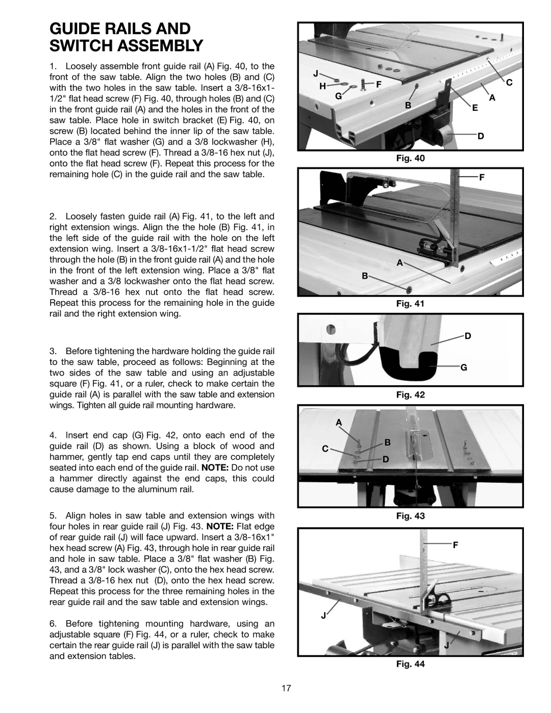
1. Loosely assemble front guide rail (A) Fig. 40, to the |
front of the saw table. Align the two holes (B) and (C) |
with the two holes in the saw table. Insert a |
1/2" flat head screw (F) Fig. 40, through holes (B) and (C) |
in the front guide rail (A) and the holes in the front of the |
saw table. Place hole in switch bracket (E) Fig. 40, on |
screw (B) located behind the inner lip of the saw table. |
Place a 3/8" flat washer (G) and a 3/8 lockwasher (H), |
onto the flat head screw (F). Thread a |
onto the flat head screw (F). Repeat this process for the |
remaining hole (C) in the guide rail and the saw table. |
2. Loosely fasten guide rail (A) Fig. 41, to the left and |
right extension wings. Align the the hole (B) Fig. 41, in |
the left side of the guide rail with the hole on the left |
extension wing. Insert a |
through the hole (B) in the front guide rail (A) and the hole |
in the front of the left extension wing. Place a 3/8" flat |
washer and a 3/8 lockwasher onto the flat head screw. |
Thread a |
Repeat this process for the remaining hole in the guide |
rail and the right extension wing. |
3. Before tightening the hardware holding the guide rail |
to the saw table, proceed as follows: Beginning at the |
two sides of the saw table and using an adjustable |
square (F) Fig. 41, or a ruler, check to make certain the |
guide rail (A) is parallel with the saw table and extension |
wings. Tighten all guide rail mounting hardware. |
4. Insert end cap (G) Fig. 42, onto each end of the |
J
H![]()
![]() FC
FC
GA
BE
D
Fig. 40
F
A
B
Fig. 41
![]() D
D
G
Fig. 42
A
guide rail (D) as shown. Using a block of wood and |
C
B
hammer, gently tap end caps until they are completely |
seated into each end of the guide rail. NOTE: Do not use |
a hammer directly against the end caps, this could |
cause damage to the aluminum rail. |
5. Align holes in saw table and extension wings with |
four holes in rear guide rail (J) Fig. 43. NOTE: Flat edge |
of rear guide rail (J) will face upward. Insert a |
hex head screw (A) Fig. 43, through hole in rear guide rail |
and hole in saw table. Place a 3/8" flat washer (B) Fig. |
43, and a 3/8" lock washer (C), onto the hex head screw. |
Thread a |
Repeat this process for the three remaining holes in the |
rear guide rail and the saw table and extension wings. |
6. Before tightening mounting hardware, using an |
adjustable square (F) Fig. 44, or a ruler, check to make |
certain the rear guide rail (J) is parallel with the saw table |
and extension tables. |
![]() D
D
Fig. 43
F
J
J
Fig. 44
17
