4.![]() WITH A MINIMUM OF TWO PEOPLE, CAREFULLY TURN THE SAW AND STAND UPRIGHT AS SHOWN IN FIG. 10. Carefully push down on the top of the saw until the stand legs adapt to the floor surface and firmly tighten all stand mounting hardware.
WITH A MINIMUM OF TWO PEOPLE, CAREFULLY TURN THE SAW AND STAND UPRIGHT AS SHOWN IN FIG. 10. Carefully push down on the top of the saw until the stand legs adapt to the floor surface and firmly tighten all stand mounting hardware.
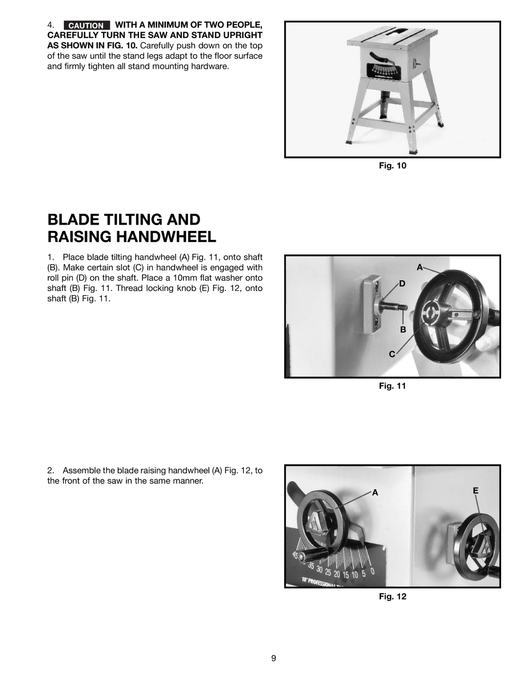
BLADE TILTING AND RAISING HANDWHEEL
1.Place blade tilting handwheel (A) Fig. 11, onto shaft
(B). Make certain slot (C) in handwheel is engaged with roll pin (D) on the shaft. Place a 10mm flat washer onto shaft (B) Fig. 11. Thread locking knob (E) Fig. 12, onto shaft (B) Fig. 11.
2.Assemble the blade raising handwheel (A) Fig. 12, to the front of the saw in the same manner.
Fig. 10
A![]()
![]() D
D
B
C
Fig. 11
![]() AE
AE
Fig. 12
9