Ethernet Communication Module
2.3 LED Indicators
Indicator | Color | Indication |
POWER | Green | Power indication |
|
|
|
Red | Communication status of the series port | |
|
|
|
100M | Orange | Network connection status |
|
|
|
LINK | Green | Network communication speed |
|
|
|
2.4
Terminal No. | Definition | Explanation | |
|
|
|
|
| 1 | Tx+ | Positive pole for data transmission |
|
|
|
|
| 2 | Tx- | Negative pole for data transmission |
|
|
|
|
| 3 | Rx+ | Positive pole for data receiving |
|
|
|
|
| 6 | Rx- | Negative pole for data receiving |
|
|
|
|
| 4, 5, 7, 8 | - | N/C |
|
|
|
|
3 Installation & Wiring
This section gives instructions on how to connect
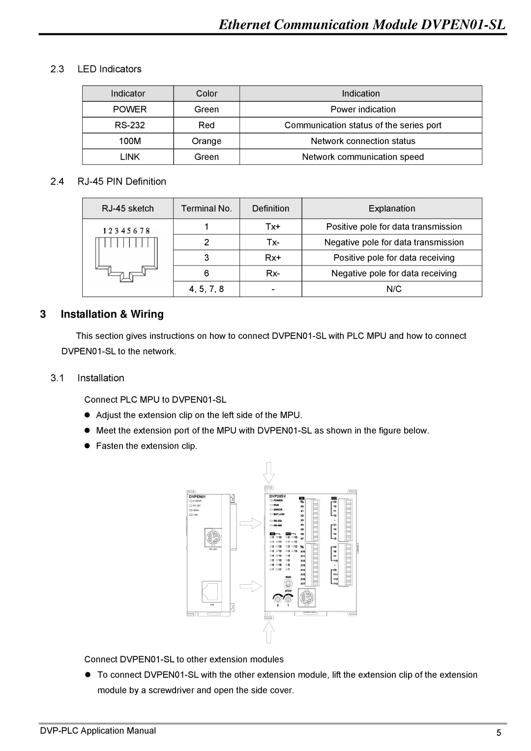
3.1Installation
Connect PLC MPU to
zAdjust the extension clip on the left side of the MPU.
zMeet the extension port of the MPU with
zFasten the extension clip.
DVPEN01 | DVP28SV |
POWER |
|
| |
100M |
|
LINK |
|
|
LAN
Connect
zTo connect
5 |